Plasma waste incinerator and incineration system thereof

A waste incinerator and plasma technology, applied in the direction of incinerator, combustion method, combustion type, etc., can solve the problems of low service life, short service life of electrodes, complicated process, etc., achieve the effect of increasing service life and ensuring high efficiency

Active Publication Date: 2018-07-06
苏州新耀环保科技有限公司
View PDF18 Cites 2 Cited by
  • Summary
  • Abstract
  • Description
  • Claims
  • Application Information

AI Technical Summary

Problems solved by technology

[0002] Existing waste disposal systems usually use methods such as ordinary incineration and burial. This method of waste disposal, especially for low- and medium-level radioactive waste, medical waste, and urban waste, has secondary pollution, complex processes, and selective waste disposal. However, in the existing plasma treatment equipment, such as the invention patent with the patent announcement number of CN 103493601B, a plasma torch is disclosed, which uses a ceramic coating layer as a diversion bushing, the ionization effect is poor, and the service life of the electrode is relatively short, basically about 6 days. Another example is the invention patent of CN103503579B, which discloses a high-performance induction plasma torch. There is a problem that the anode position will be corroded due to ionization reaction, the service life is low, and the combustion efficiency is low

Method used


Image

  • Plasma waste incinerator and incineration system thereof
  • Plasma waste incinerator and incineration system thereof
  • Plasma waste incinerator and incineration system thereof

Examples


Embodiment 1

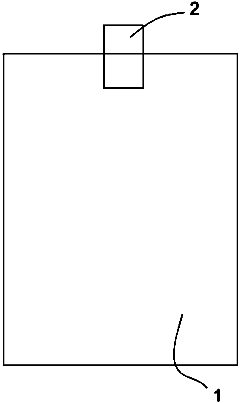
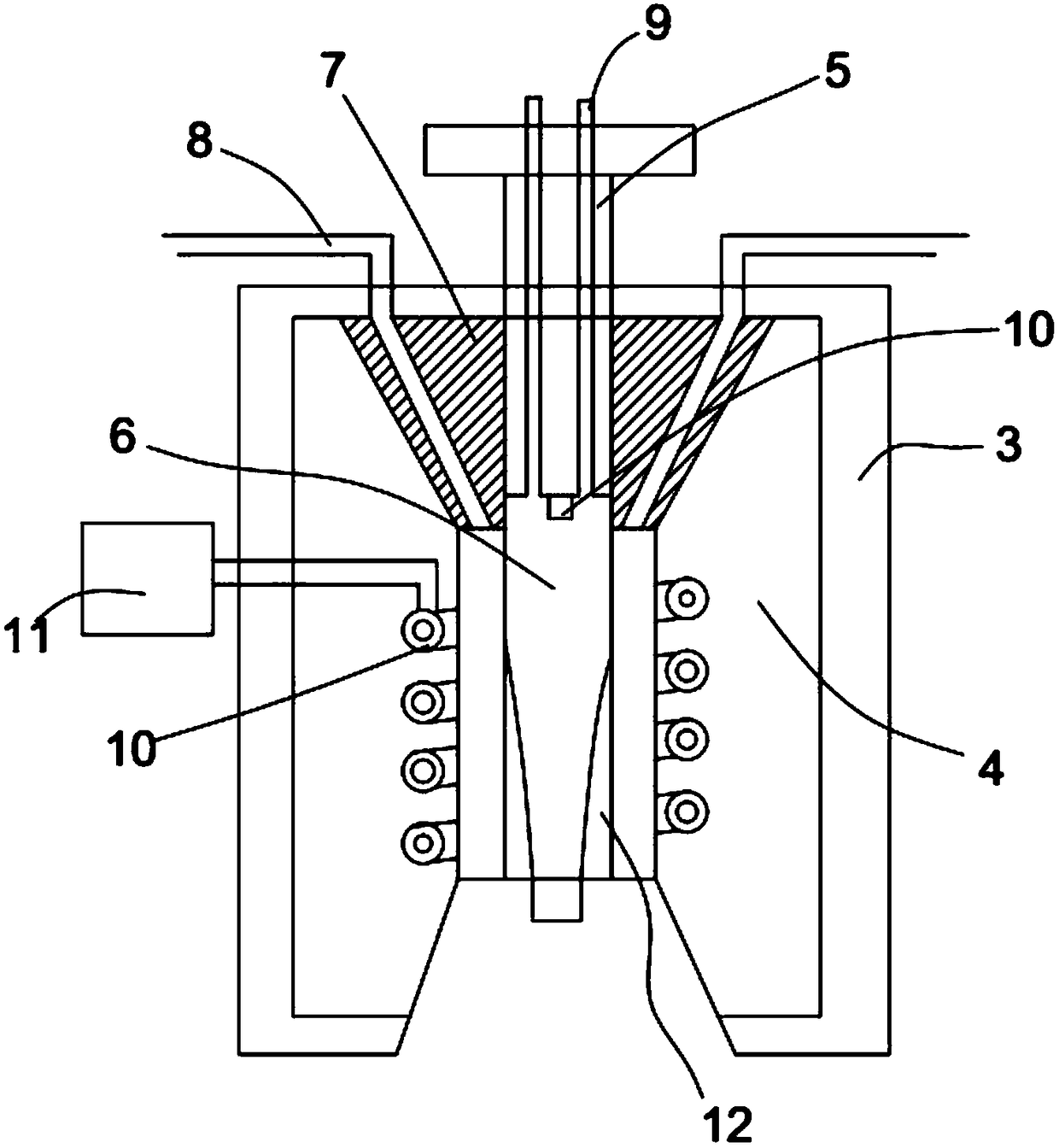
[0033] The present invention proposes a plasma waste incinerator 15, comprising a furnace body 1, a plasma torch 2 is provided on the top of the furnace body 1, and the plasma torch 2 includes a pipe body 3, and the pipe body 3 is provided with a An anode 4 and a cathode 5; the center of the anode 4 is provided with an ionization chamber 6, and the upper part of the ionization chamber 6 is an inverted tapered groove, and a gas guide block 7 is arranged in the tapered groove; the cathode 5 passes through the The gas guide block 7 extends to the upper part of the ionization chamber 6; the first air guide tube 8 is connected to the gas guide block 7, and the first air guide tube 8 is arranged along the gas guide block 7 and directed to the ionization chamber. cavity 6; at least one second air duct 9 is connected to the cathode 5; a trigger electrode 10 is provided at the bottom of the cathode 5.

[0034] Wherein, the anode 4 is made of semiconductor silicon material, the cathode ...

Embodiment 2

[0036] The basic structure of this embodiment is the same as that of Embodiment 1, the difference is that the materials of the anode 4 and the cathode 5 are selected from traditional materials, and the service life of the final structure is greatly reduced.

Embodiment 3

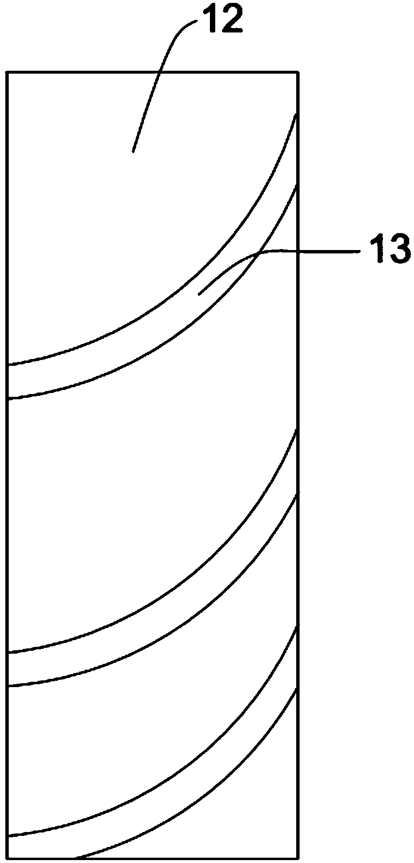
[0038] The basic structure of this embodiment is the same as that of Embodiment 1, the difference is that the ionization chamber 6 is a cylindrical chamber, and the convex layer 12 and the slit are not provided in the ionization chamber 6, and the temperature of the final reaction zone is reduced, which affects Thermal efficiency.


PUM


Abstract

The invention provides a plasma waste incinerator and an incineration system thereof. The incinerator comprises an incinerator body, the top of the incinerator body is provided with a plasma torch, the plasma torch comprises a pipe body, and the pipe body is internally provided with a positive electrode and a negative electrode; an ionization cavity is formed in the center of the positive electrode, the upper portion of the ionization cavity is provided with an inverted conical groove, and the conical groove is internally provided with a gas guide block; the negative electrode penetrates through the gas guide block and extends to the upper portion of the ionization cavity; the system comprises a first combustion chamber, the plasma waste incinerator, a heat exchanger, an extremely cold spraying system, a cloth bag dust removal device and a filtration device which are connected sequentially; according to the incinerator, by using the gas guide block, it is ensured that the heat is centralized at a point efficiently during gas ionization, the high efficiency is ensured, and the service life of the plasma torch is greatly prolonged; the incineration system is used for quickly decomposing and destroying treated objects, wherein organic matter is pyrolyzed into flammable small-molecular substances, and inorganic matter is subjected to high-temperature melting to generate glass-similar residues.

Description

technical field [0001] The invention relates to the field of garbage treatment, in particular to a plasma garbage incinerator and an incineration system thereof. Background technique [0002] Existing waste disposal systems usually use methods such as ordinary incineration and burial. This method of waste disposal, especially for low- and medium-level radioactive waste, medical waste, and urban waste, has secondary pollution, complex processes, and selective waste disposal. However, in the existing plasma treatment equipment, such as the invention patent with the patent announcement number of CN 103493601B, a plasma torch is disclosed, which uses a ceramic coating layer as a diversion bushing, the ionization effect is poor, and the service life of the electrode is relatively short, basically about 6 days. Another example is the invention patent of CN103503579B, which discloses a high-performance induction plasma torch. There is a problem that the anode position will be corr...

Claims


Application Information

Patent Timeline
Patent Type & Authority Applications(China)
IPC IPC(8): F23G5/02F23G5/44F23J15/02
CPCF23G5/02F23G5/44F23J15/025
Inventor 张帅
Owner 苏州新耀环保科技有限公司
Why Eureka
Try Eureka