Multifunctional material distribution equipment and application method thereof

A multi-functional, cloth technology, applied in supply devices, manufacturing tools, etc., can solve the problems of large space occupied, low effective utilization of resources, and poor commonality of cloth equipment, and achieve the effect of improving efficiency.

Pending Publication Date: 2018-07-13
GUANGDONG SUMMIT CERAMIC CO LTD +1
View PDF9 Cites 16 Cited by
  • Summary
  • Abstract
  • Description
  • Claims
  • Application Information

AI Technical Summary

Problems solved by technology

[0003] People in the industry know that the existing technologies for making the above-mentioned types of ceramic tile bodies are all prepared by different distributing equipment, and the commonality between different distributing equipment is not strong. They want to produce products with different processes or materials on the same equipment to achieve comprehensive Performance improvements are difficult to achieve
Therefore, the manufacturer must plan the supporting production line according to the process type of the product or the performance of the material, cost constraints, etc., so that the manufacture of pr

Method used


Image

  • Multifunctional material distribution equipment and application method thereof
  • Multifunctional material distribution equipment and application method thereof
  • Multifunctional material distribution equipment and application method thereof

Examples


Embodiment approach 1

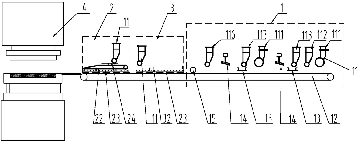
[0064] Step 1. Start the first three in the lower hopper 11 of the first powder drop conveying module 1, and drop the powder of predetermined color on the main belt 12 that accepts and transmits the raw material, and distribute powder with a predetermined thickness , during the relative movement of the molding device during the downcutting stop time and the carrier transmission, each slice of the first group of molding devices 14 blocks the predetermined pattern layout on the main belt 12 during the downcutting process, forming powder accumulation and pits , and then through the fourth and fifth lower hoppers, wherein the powder of the predetermined amount of predetermined color is filled, and then the second set of molding device 14 cuts and blocks, and finally filled into the predetermined color predetermined material in the sixth lower hopper A certain amount of powder is flattened by the powder leveling device 15 to form the first layer of pattern raw material and conveyed ...

Embodiment approach 2

[0068]Step 1. Start the first three in the lower hopper 11 of the first powder drop conveying module 1, and drop the powder of predetermined color on the main belt 12 that accepts and transmits the raw material, and distribute powder with a predetermined thickness , during the relative movement of the molding device during the downcutting stop time and the carrier transmission, each slice of the first group of molding devices 14 blocks the predetermined pattern layout on the main belt 12 during the downcutting process, forming powder accumulation and pits , and then filled with the powder of the predetermined color and predetermined amount in the fourth and fifth lower hoppers, and then through the cutting and blocking effect of the second group of molding devices 14, and finally filled into the predetermined color predetermined amount in the sixth lower hopper The powder material is formed the first layer of pattern raw material after being flattened by the powder leveling dev...

Embodiment approach 3

[0073] Step 1. The push frame 23 of the feeding module 3 drives the feeding grid 32 to move forward. The feeding grid here is a receiving type conveying grid, which accepts the raw materials falling from the upper lower hopper 11 during the moving process;

[0074] Step 2. After the accepting conveying grid accepts the laid raw materials, the push rack 23 drives the feeding grid 32 to push to the forming device. Descending, the predetermined raw material received by the conveying grid falls on the surface of the lower mold core of the mold cavity and falls into the mold cavity with the falling mold, and the push frame 23 returns. adobe;

[0075] Step 3: The push frame 23 returns to the initial position, the conveying grid continues to accept the raw materials of step 1, repeat the above step 2, and at the same time push the bricks pressed in the previous step out of the press, and transfer them to the drying machine under the conveying of the subsequent process. The kiln is c...


PUM


Abstract

The invention discloses multifunctional material distribution equipment and an application method thereof. The multifunctional material distribution equipment comprises a first powder falling conveying module. The first powder falling conveying module comprises discharging hoppers. Modeling devices are arranged between the discharging hoppers. A vibration screen is arranged between each modeling device and the corresponding discharging hopper in front of the modeling device, and the position adjacent to a feeding module is provided with a material flattening device. A main belt is arranged below the vibration screens, and the end portion of the main belt is adjacent to a forming device. The feeding module and a second powder falling conveying module are arranged above the main belt, and the feeding module is closely adjacent to the first powder falling conveying module. The second powder falling conveying module comprises discharging hoppers, a conveying belt, a transfer hopper and a pushing frame, wherein the lower portion of the conveying belt is connected with the pushing frame, and the discharging hoppers are arranged above the conveying belt. The feeding module comprises discharging hoppers, a feeding grid and a pushing frame, wherein the lower portion of the feeding grid is connected with the pushing frame. According to the multifunctional material distribution equipmentand the application method thereof, the production efficiency is improved, production equipment input management, maintenance and cost in the related technology are reduced, and the occupied space isgreatly saved.

Description

technical field [0001] The invention relates to the field of architectural ceramic tiles, in particular to a multifunctional distributing equipment and a method for using the same. Background technique [0002] In the decoration of modern buildings, the top-ranking decorative materials are none other than high-grade natural stones with natural patterns and shapes, especially high-grade marbles with fine and attractive textures. With people's emphasis on scarce resources and environmental protection, using ceramic tiles to imitate stone products has become a major trend in home furnishing and decoration, and is widely favored by people. The specific subdivisions of ceramic tile products include micro-powder polishing, inkjet Glazed tiles, antique tiles, polished tiles, etc., and in recent years, new materials or cost-effective or products such as whole-body ceramic tiles that are close to the overall texture of natural stone, and ceramic products containing surface dry partic...

Claims


Application Information

Patent Timeline
IPC IPC(8): B28B13/02
CPCB28B13/023
Inventor 叶德林简润桐陈章武梁以坚冼定邦
Owner GUANGDONG SUMMIT CERAMIC CO LTD
Why Eureka
Try Eureka