Connecting structure of semiconductor microwave generator

A microwave generator and connection structure technology, which is applied in microwave heating, heating fuel, lighting and heating equipment, etc., can solve the problems that the discharge tube is easily corroded, affects the operation of the equipment, and the plasma is unstable

Pending Publication Date: 2018-07-13
栗斌
View PDF7 Cites 0 Cited by
  • Summary
  • Abstract
  • Description
  • Claims
  • Application Information

AI Technical Summary

Problems solved by technology

[0004] Aiming at the deficiencies in the prior art, the purpose of the present invention is to provide a semiconductor microwave generator connection structure to solve the problem of the traditional resonant cavity design in the transmission of coupling coils and coaxial wires in the process of microwave signal transmission in the prior art. The plasma in the medium is too unstable, which makes the fluctuation noise of the microwave source large and the resonance frequency is low, which seriously affects the operation of the equipment. When the equipment is used for too long, the discharge tube inside the resonant cavity is easily corroded, which reduces the life of the discharge tube by 20- 30. Therefore, the efficiency of semiconductor microwave generators is also severely reduced, leading to the problem of increased cost of use

Method used


Image

  • Connecting structure of semiconductor microwave generator
  • Connecting structure of semiconductor microwave generator
  • Connecting structure of semiconductor microwave generator

Examples


Embodiment 1

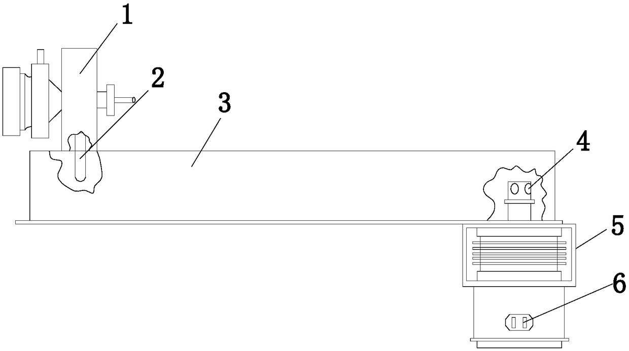
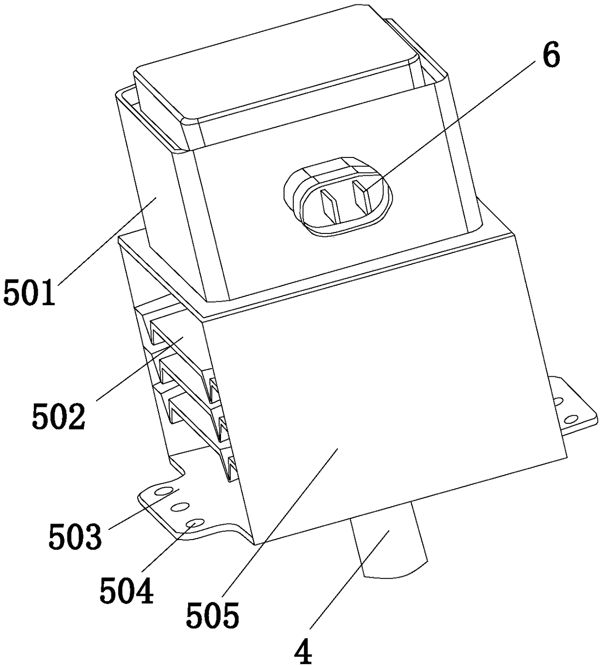
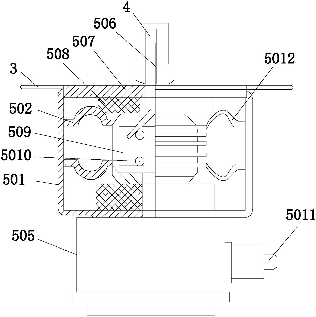
[0031] see Figure 1-Figure 9 , the present invention provides a semiconductor microwave generator connection structure, which structure includes a resonant cavity 1, a resonant cavity antenna 2, a waveguide 3, an antenna 4, a semiconductor microwave generator 5, and a power interface 6, and one end of the waveguide 3 passes through The resonant cavity antenna 2 is connected with a resonant cavity 1, the resonant cavity 1 is installed in the microwave oven through a hinge provided and fixedly connected with screws, the other end of the waveguide 3 is equipped with a semiconductor microwave generator 5, and the resonant cavity Cavity antenna 2 adopts signal connection with antenna 4 through waveguide 3, and described power supply interface 6 is welded on the outer surface of the lower end of semiconductor microwave generator 5, and described semiconductor microwave generator 5 is composed of energy exporter 501, heat sink 502, chassis 503 , threaded hole 504, generator housing ...

Embodiment 2

[0034] see Figure 1-Figure 10 The lead-out cable 5011 is sequentially provided with a core wire 50111, a core wire insulation layer 50112, a first semiconductor layer 50113, an insulation layer 50114, a second semiconductor layer 50115, a metal shielding layer 50116, and a yarn wrap protection layer 50117 from inside to outside. The inside of the first semiconductor layer 50113 is evenly installed with three core wires 50111 and surrounds them to form a triangular structure. The outer surface is laminated with a second semiconductor layer 50115, a metal shielding layer 50116, and a yarn-wrapped protective layer 50117 in sequence.

[0035] The core wire insulation layer 50112, the first semiconductor layer 50113, the insulation layer 50114, the second semiconductor layer 50115, the metal shielding layer 50116, and the gauze protective layer 50117 provided with the outgoing cable 5011 can effectively prevent the equipment from being affected by the surrounding environment , un...


PUM


Abstract

The invention discloses a connecting structure of a semiconductor microwave generator. The connecting structure comprises a resonant cavity, a resonant cavity antenna, a waveguide tube, an antenna, the semiconductor microwave generator and a power interface. Compared with a traditional resonant cavity, a shaft bracket is arranged in the center of the resonant cavity, the thickness of a coupling coil is large, the internal diameter of the resonant cavity is small, high-stability plasma is provided for the coupling coil and a coaxial wire designed through the cavity, the signal-to-noise ratio ofmicrowaves is larger than 2,000, it is shown that fluctuation noise from a microwave source barely exists, the tolerance of the plasma for the change of operating conditions is greatly improved, andthe resonant frequency is improved; and a quartz discharge tube in the resonant cavity is connected with a cooling water inlet and a cooling water outlet, the discharge tube is slightly corroded afterbeing used for 30 d, the peak trailing degree of a sulfur channel is also reduced, thus, the discharge tube does not need to be frequently replaced, the discharge tube only needs to be replaced onceevery month commonly after running continuously, and the service life is effectively prolonged while equipment running is not affected.

Description

technical field [0001] The invention relates to a connection structure of a semiconductor microwave generator, which belongs to the field of microwave ovens for household appliances. Background technique [0002] A microwave oven is a modern cooking stove that heats food with microwaves, which are electromagnetic waves. A microwave oven is composed of a power supply, a magnetron, a control circuit, and a cooking cavity. The power supply provides a high voltage of about 4000 volts to the magnetron. Under the excitation of the power supply, the magnetron continuously generates microwaves, and then couples into the cooking cavity through a waveguide system. , near the entrance of the cooking cavity, there is a rotatable stirrer, because the stirrer is a fan-shaped metal, which can reflect the microwave in all directions after rotating, so it can evenly distribute the microwave energy in the cooking cavity, To heat food, the power range of microwave ovens is generally 500-1000 ...

Claims


Application Information

Patent Timeline
Patent Type & Authority Applications(China)
IPC IPC(8): F24C7/02F24C7/06H05B6/72
CPCF24C7/067H05B6/6402H05B6/72H05B2206/04
Inventor 林声坤陈炳哲刘小静
Owner 栗斌
Why Eureka
Try Eureka