
Laser rangefinder verification device based on principle of error cancellation and verification method thereof

A laser rangefinder and laser interferometer technology, applied in radio wave measurement systems, instruments, etc., can solve the problems of poor measurement stability, difficult operation, difficult beam position constraints, etc., to improve the multiplier efficiency and high measurement accuracy. , the effect of good measurement stability

Pending Publication Date: 2018-07-17
TIANJIN INST OF METROLOGICAL SUPERVISION & TESTING
View PDF0 Cites 23 Cited by
  • Summary
  • Abstract
  • Description
  • Claims
  • Application Information

AI Technical Summary

Problems solved by technology

[0004] In addition to the limitation of the measurement range by the verification code, there are still some problems in the indoor large-space detection method: ①The cost is very expensive and the construction is difficult, which is difficult for general testing institutions. Taking Zhejiang Institute of Metrology as an example, the indoor length of 50 meters The cost of the standard device is as high as 1.425 million yuan; ②It covers a large area, and it is difficult for general laboratory conditions to meet the space requirements of tens of meters or even hundreds of meters; ③The detection efficiency is low, such as the requirements of JJG966-2010 Handheld Laser Rangefinder Verification Regulations , To detect the indication error within 50 meters, at least 12 points need to be measured, and the distance that a tester needs to walk to measure a laser rangefinder is close to 600 meters, and the testers are overwhelmed
However, in the actual verification process, there are many problems in the field baseline field detection: ① It is very difficult to establish a baseline field, and it is very difficult to select hundreds or even thousands of meters of straight areas in cities without natural obstacles and interference from animals and animals
② The occasions that meet the above conditions must be found far away from the city, which brings great inconvenience to the verification work, and consumes time, energy and energy
③The field baseline field is arranged on the ground or on ground piles. The erection and alignment of instruments and reflectors are very laborious. Not only does it require more than two people to operate, but it is often impossible to obtain correct and reliable results due to inaccurate alignment.
④ Operations in the field under natural climate conditions are greatly affected by the weather. Due to weather changes, the verification efficiency is often low, and the work quality cannot be improved.
Existing problems: ① In the long-distance range, the optical path calibration technology is very difficult, and at the same time, the flatness of the large flat mirror and the parallelism between the mirrors will introduce a large measurement uncertainty, and the stability of the measurement system is poor
②The accuracy of the incident angle of the rangefinder and the parallelism between the plane mirrors will seriously affect the accurate position of the laser beam in the three-dimensional space, making it extremely difficult to adjust the optical path and capture the target spot by the reflective target, and the measurement is not easy to implement
③The measurement method of the system is still a discrete measurement and does not have the capability of continuous measurement in a large range
[0009] (2) In 2013, Li Qian of Xi'an University of Technology and others used a right-angle mirror group to fold the light multiple times in the dynamic space, shortened the 50m measurement distance to a space of more than ten meters, and calibrated the optical path of the total station to detect the handheld In 2016, Jiangsu Province Surveying and Mapping Products Quality Supervision and Inspection Station proposed to use right-angle prisms to perform optical path folding and simulate length baseline field verification of total stations. At the level of technical difficulty evaluation, no in-depth research has been conducted
The application number is 2013100161742, and the patent name is "Handheld Laser Rangefinder Verification System and Verification Method". Problems: ① The reflection characteristics of the right-angle mirror group and the right-angle prism ensure that the laser beams remain parallel in the horizontal plane, However, there is still the problem of ensuring beam parallelism in the vertical plane, especially during the dynamic movement of the pallet, it is very difficult to constrain the position of the beam
② Three sets of right-angle reflective devices are required to realize four times the optical path in the system, with a total of 6 reflectors, and the structure is too complicated
[0012] To sum up, the current optical path multiplication method still lacks a high-accuracy measurement method that can be applied to front-line detection. There are problems such as difficult optical path calibration technology, complex system structure, poor measurement stability, and difficult operation. The position constraint during the folding process is the key to improving the measurement accuracy, especially how the reflective device can improve the adaptive ability of the laser beam during the dynamic movement process needs to be further explored

Method used


Image

  • Laser rangefinder verification device based on principle of error cancellation and verification method thereof
  • Laser rangefinder verification device based on principle of error cancellation and verification method thereof
  • Laser rangefinder verification device based on principle of error cancellation and verification method thereof

Examples


Embodiment Construction

[0033] The present invention will be described in detail through the following examples, which are illustrative rather than restrictive, and cannot limit the protection scope of the present invention.

[0034] 1. Research methods:

[0035] (1) Optical path calibration and error cancellation method

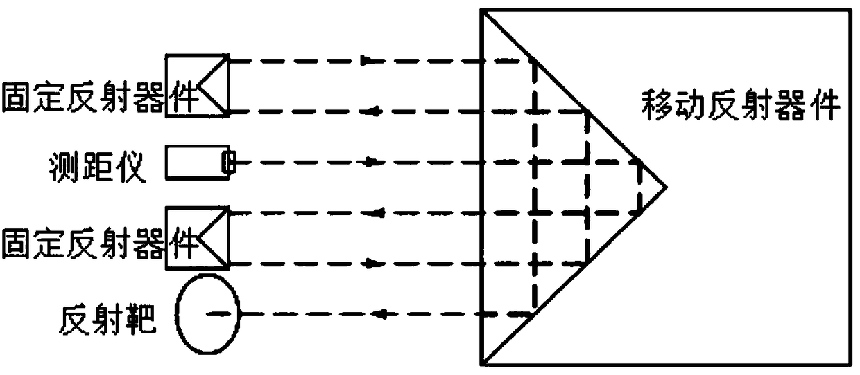
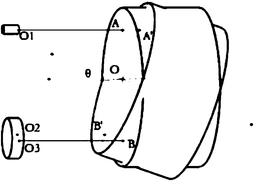
[0036] like figure 2 As shown, in the ideal posture, the laser rangefinder emits a laser beam at O1 and hits point A of the mobile reflective device, and the beam is reflected from point B to point O3 of the fixed reflective device in parallel after reflection. The light beam and the optical axis of the reflective device are deflected by an angle of θ, causing the light beam to be incident on point A' and reflected from point B' to point O2. Suppose the optical path from O1 to A is a, the optical path from O1 to A' is a', the optical path from O2 to B' is b', and the optical path from O3 to B is b. Symmetry, no matter how the azimuth angle θ changes: a+b=a'+b', the measurement ...


PUM


Abstract

The invention belongs to the technical field of geometric measurement device verification devices, relates to a laser rangefinder verification device, and particularly relates to a laser rangefinder verification device based on the principle of error cancellation and a verification method thereof. The laser rangefinder verification device comprises a verification table. A fixing adjustment deviceis installed in the fixed end of the verification table. The fixing adjustment device is used for fixing a laser rangefinder to be verified. After the fixing adjustment device fixes a laser rangefinder to be verified, a self-walking target vehicle is installed in the verification table. A mobile reflection apparatus is installed in the self-walking target vehicle. A reflection target and at leastone fixed reflection apparatus are installed beside the fixing adjustment device at the fixed end of the verification table. A measurement reflector is installed at the rear end of the mobile reflection apparatus inside the self-walking target vehicle. A laser interferometer is installed at the end of the verification table away from the fixed end. The measurement reflector is used for reflectinga laser beam emitted by the laser interferometer.

Description

technical field [0001] The invention belongs to the technical field of verification devices for geometric measuring devices, and relates to a verification device for a laser range finder, in particular to a verification system and a verification method for a laser range finder based on the principle of error cancellation. Background technique [0002] With the continuous development of geometric quantity testing technology, precision measurement technology has continuously developed from conventional size measurement to large-scale measurement. Especially in the past 20 years, the measurement range of precision measuring instruments has reached tens of meters, tens of meters or even hundreds of meters, and is widely used. It is used in large-scale equipment manufacturing fields such as spacecraft, aircraft, ships, wind power, and hydropower. At present, the domestically used instruments with a measurement range greater than 50m include: laser interferometer (≥60m), laser tra...

Claims


Application Information

Patent Timeline
IPC IPC(8): G01S7/497
CPCG01S7/497
Inventor 刘红光路瑞军李青
Owner TIANJIN INST OF METROLOGICAL SUPERVISION & TESTING
Learn More