Heating furnace pulse control system and method

A pulse control and heating furnace technology, applied in the field of metallurgy, can solve the problems of weak heat radiation ability, inability to guarantee the high-load combustion state of the burner, and high energy consumption per ton of steel

Inactive Publication Date: 2018-07-24
WUHAN IRON & STEEL ENG TECH GROUP
View PDF6 Cites 9 Cited by
  • Summary
  • Abstract
  • Description
  • Claims
  • Application Information

AI Technical Summary

Problems solved by technology

After the temperature regulator calculates the rated gas flow rate, it cannot ensure that the burner is always in a high-load combustion state when it is distributed to each burner, so that the flame emitted by the burner is short and the heat radiation ability is weak, and only local high temperature will be generated near the furnace wall , the temperature in the middle of the furnace body is relatively low, the billet is heat...

Method used


Image

  • Heating furnace pulse control system and method
  • Heating furnace pulse control system and method
  • Heating furnace pulse control system and method

Examples


Embodiment 1

[0025] A heating furnace pulse control system provided by an embodiment of the present invention, the upper section of the system uses a flat flame burner for heating, the lower section uses a low NOx burner, and three burners are respectively installed at the north and south ends of the lower section ;

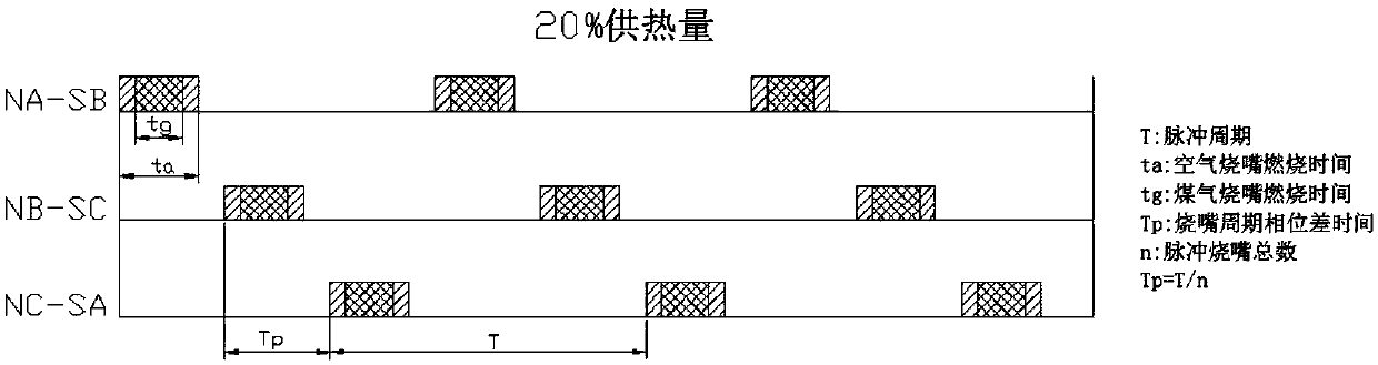
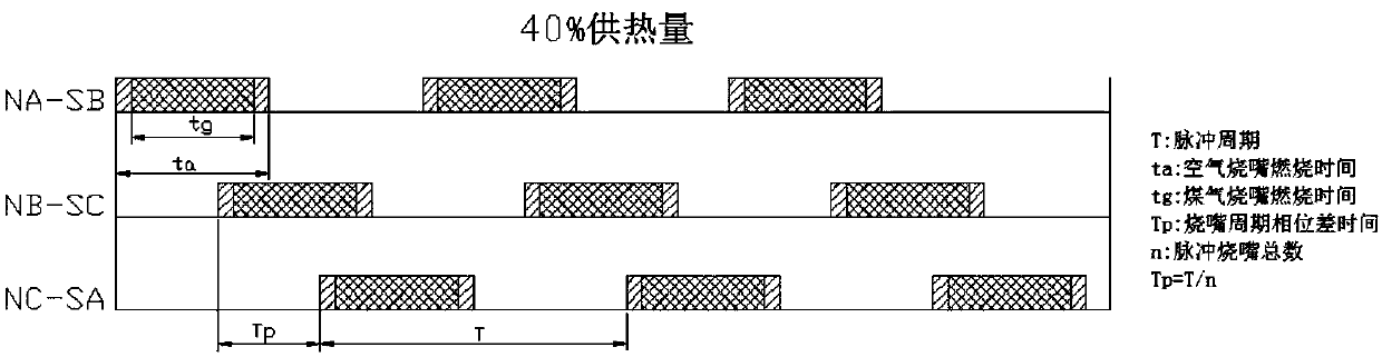
[0026] The pulse control system of the heating furnace adopts double-crossing limit and pulse control technology, and the six burners in the lower section work in sequence with two crossed burners as a group.

[0027] The control system of this scheme is based on the original double-crossing limiter, adding pulse control technology. The difference from conventional pulse control is that the 6 burners in the lower section no longer use a single burner cycle switch mode, but use 2 burners that are crossed. The mouth is a group and moves sequentially, such as figure 2 shown.

[0028] Taking the pulse period of 60s and heating demand of 20% as an example, analyze the status of...

Embodiment 2

[0044] Based on the same inventive concept, this embodiment provides a heating furnace pulse control method. The problem-solving principle of the heating furnace pulse control method is similar to a heating furnace pulse control system. Therefore, the implementation of the heating furnace pulse control method can be found in the heating furnace pulse The implementation of the control system will not be repeated here.

[0045] see Figure 5 The heating furnace pulse control method provided by this program is applied to any heating furnace pulse control system proposed in the first embodiment above. The upper section of the heating furnace pulse control system uses flat flame burners for heating, and the lower section uses low NOx burners. mouth, three burners are respectively arranged at the north and south ends of the lower section; the method includes:

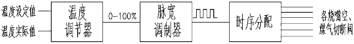
[0046] Step 201: Send the pulse duty ratio of the output of the temperature regulator to a pulse width modulator, and the ...


PUM


Abstract

The invention provides a heating furnace pulse control system and method and belongs to the technical field of metallurgy. The upper section of the system conducts heat supply through flat flame burners, and the lower section of the system conducts heat supply through NOx burners. The three burners are arranged at the south end of the lower section, and the three burners are arranged at the northend of the lower section. The heating furnace pulse control system integrates the double-cross amplitude limit technology and the pulse control technology. Every two crossed burners of the six burnersof the lower section serve as a group, and the three groups of the burners work in sequence. According to the heating furnace pulse control system, the pulse combustion technology is adopted; as allthe burners work under high-load conditions, extrusive flames are long, and the thermal radiation capacity is high; thus, steel blanks can be heated uniformly, and the burners can be protected againstbackfire; moreover, through periodic switching of the pulse burners, the furnace atmosphere can be blended sufficiently, the gas thermal convection capability is enhanced at high radiation, and the heating uniformity of the plate blanks is further improved.

Description

technical field [0001] The invention relates to the technical field of metallurgy, in particular to a heating furnace pulse control system and control method. Background technique [0002] The heating furnace is one of the important equipment in the metallurgical industry. Its function is to heat the billet to meet the requirements of subsequent rolling treatment. The performance of the heating furnace directly affects the rolling quality of the billet. The combustion atmosphere in the furnace, the temperature of the slab out of the furnace, the temperature uniformity of the slab, and the gas consumption have always been important indicators to measure the performance of the heating furnace for steel burning. These parameters are closely related to the combustion control system of the heating furnace. Therefore, the research on the combustion system of the heating furnace is a must very necessary. [0003] At present, the combustion process of the heating furnace has a doub...

Claims


Application Information

Patent Timeline
IPC IPC(8): F27D19/00B21B45/00
CPCB21B45/004F27D19/00F27D2019/004
Inventor 黄巍马珺
Owner WUHAN IRON & STEEL ENG TECH GROUP
Why Eureka
Try Eureka