On-chip integrated part reflector based on partial transmission-type corner reflector group
A technology of corner mirrors and integrated parts, which is applied in the field of on-chip integrated partial reflectors, can solve the problems that the width of the etching groove cannot be too large, it is difficult to ensure the manufacturing accuracy, and the etching quality cannot be guaranteed, so as to achieve multiple degrees of freedom in the selection of design parameters , The effect of large tolerance and simple structure
- Summary
- Abstract
- Description
- Claims
- Application Information
AI Technical Summary
Problems solved by technology
Method used
Image
Examples
Embodiment 1
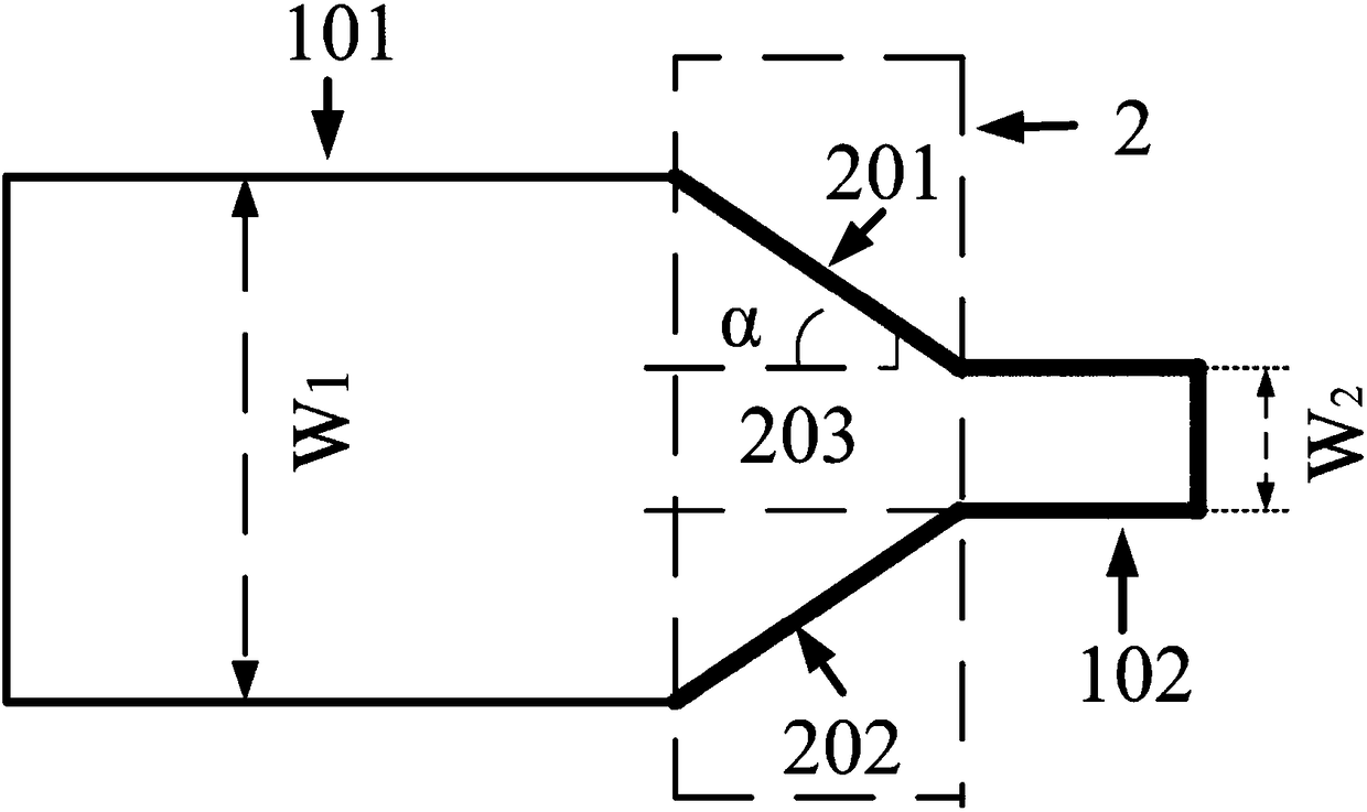
[0068] Such as image 3 As shown, the on-chip integrated partial reflector includes an input waveguide 101 , a transmissive corner mirror group 2 and an output waveguide 102 . Wherein the partial transmissive corner reflector group 2 is composed of a first reflector 201, a central transmissive area 203 and a second reflector 202 arranged in sequence, the reflective surfaces of the first reflector 201 and the second reflector 202 face the input waveguide 101, partly The input end of the transmissive corner mirror group 2 is connected to the input waveguide 101, and the output port is connected to the output waveguide 102, and the width of the input waveguide 101 is greater than the width of the output waveguide 102; the width of the input end of the partial transmission corner mirror group 2 is the same as that of the input waveguide 101 , the width of the output end is the same as that of the output waveguide 102 .
[0069] The incident light entering from the input waveguide...
Embodiment 2
[0074] Such as Figure 7 As shown, the on-chip integrated partial reflector includes an input waveguide 101 , a partially transmissive corner mirror group 2 , an output waveguide 102 , a beam expander 3 and an energy coupler 4 . The partial transmission corner mirror group 2 is composed of a first mirror 201 , a central transmission area 203 and a second mirror 202 arranged from top to bottom, and the beam expander 3 and the energy coupler 4 are tapered waveguide structures.
[0075] Considering the simplification of the design, the tapered waveguide structure in this embodiment adopts the form that the waveguide width changes linearly with the waveguide length. The width of the input end of the beam expander 3 is the same as that of the input waveguide 101, the width of the output end is the same as that of the input end of the partial transmission type corner reflector group 2, and the width of the input end of the energy coupler 4 is the same as that of the output end of th...
Embodiment 3
[0078] Such as Figure 9 As shown, the on-chip integrated partial reflector includes an input waveguide 101 , a partially transmissive corner mirror group 2 , an output waveguide 102 , a beam expander 3 and an energy coupler 4 . Among them, the partial transmission corner mirror group 2 is composed of the first mirror 201, the central transmission area 203 and the second mirror 202 connected in sequence, the energy coupler 4 is a tapered waveguide structure, and the beam expander 3 is composed of a multi-mode interference coupling waveguide Structure 301 and waveguide mode spot converter 302. The width of the input end of the beam expander 3 is the same as that of the input waveguide 101, the width of the output end is the same as that of the input end of the partial transmission type corner reflector group 2, and the width of the input end of the energy coupler 4 is the same as that of the output end of the partial transmission type corner mirror group 2 , the output port is...
PUM
 Abstract
Description
Claims
Application Information
 - R&D
- Intellectual Property
- Life Sciences
- Materials
- Tech Scout
- Unparalleled Data Quality
- Higher Quality Content
- 60% Fewer Hallucinations
Browse by: Latest US Patents, China's latest patents, Technical Efficacy Thesaurus, Application Domain, Technology Topic, Popular Technical Reports.
© 2025 PatSnap. All rights reserved.Legal|Privacy policy|Modern Slavery Act Transparency Statement|Sitemap|About US| Contact US: help@patsnap.com


