
A patterning device and method using intense pulsed light sintering

A pattern and conductive pattern technology, applied in the field of pattern forming devices, can solve problems such as poor productivity or process efficiency, difficult to apply, etc., and achieve the effects of high process and productivity, prevention of metal oxidation, and efficient formation

Active Publication Date: 2021-02-19
KOREA INST OF MACHINERY & MATERIALS
View PDF12 Cites 0 Cited by
  • Summary
  • Abstract
  • Description
  • Claims
  • Application Information

AI Technical Summary

Problems solved by technology

This process is difficult to apply to substrates with relatively large dimensions, and the productivity or process efficiency is relatively poor

Method used


Image

  • A patterning device and method using intense pulsed light sintering
  • A patterning device and method using intense pulsed light sintering
  • A patterning device and method using intense pulsed light sintering

Examples


Embodiment Construction

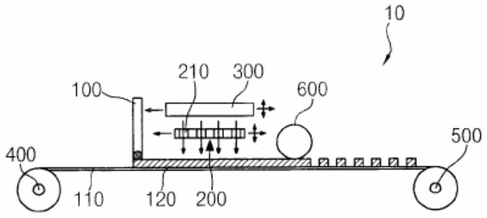
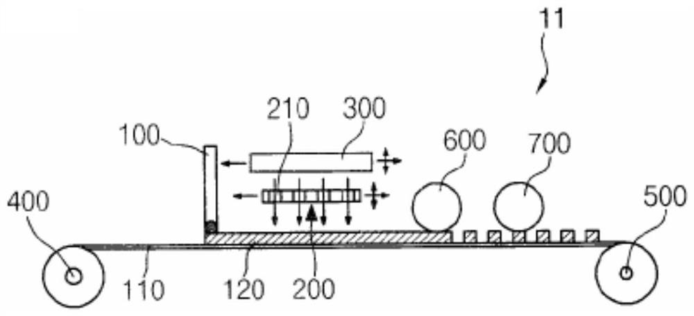
[0057] The invention will be described more fully hereinafter with reference to the accompanying drawings, in which embodiments of the invention are shown. However, this invention may be embodied in many different forms and should not be construed as limited to the embodiments set forth herein. Rather, these embodiments are provided so that this disclosure will be thorough and complete, and will fully convey the scope of the invention to those skilled in the art. In the drawings, the size and relative sizes of layers and regions may be exaggerated for clarity. It should be understood that although the terms first, second, third etc. may be used herein to describe various elements, components, regions, layers and / or sections, these elements, components, regions, layers and / or sections should not are limited by these terms. These terms are only used to distinguish one element, component, region, layer or section from another region, layer or section. Thus, a first element, co...


PUM

PropertyMeasurementUnit
diameteraaaaaaaaaa

Abstract

A pattern forming device using intense pulsed light sintering and a pattern forming method using the pattern forming device. The patterning device includes a supply roll, a coating unit, a mask, a light generating unit, and a take-up roll. Rollers are provided to provide a flexible substrate. The coating unit coats the conductive ink on the substrate. A mask is disposed on the substrate on which the conductive ink is coated, and a pattern is formed on the mask. The light generating unit irradiates light to the conductive ink through the mask to form a conductive pattern on the substrate. The take-up roller takes back the substrate on which the conductive pattern is formed.

Description

technical field [0001] The present invention relates to a pattern forming device using intense pulsed light sintering and a method of pattern forming using the pattern forming device, in particular, the present invention relates to a pattern forming device formed on a flexible substrate by intense pulsed light sintering Pattern coated with ink, and a method of pattern formation using the pattern forming device. Background technique [0002] Traditionally, in printed electronics, conductive inks are often used, in which metal powders such as gold, silver and copper are mixed with a solution. Metals are highly conductive and mechanically flexible to facilitate their use on flexible substrates. [0003] During patterning using conductive ink, thermal sintering is generally used, and during thermal sintering, the conductive ink is heated and cooled at a temperature between about 200°C and about 300°C to sinter the metal powder. [0004] However, thermal sintering is a relative...

Claims


Application Information

Patent Timeline
Patent Type & Authority Patents(China)
IPC IPC(8): H05K3/12H01L51/00H01L21/56H05K3/38B08B7/02H01L21/033H01L21/02
CPCB08B7/02H01L21/033H01L21/02H01L21/56H05K3/12H05K3/38H10K99/00
Inventor 禹奎照李泽旻权信金仁英崔荣满姜东佑金广泳
Owner KOREA INST OF MACHINERY & MATERIALS
Learn More