Apparatus for measuring diffusion coefficient during shale oil carbon dioxide huffing-puffing process and method thereof

A technology of diffusion coefficient and carbon dioxide, which is used in measurement devices, diffusion analysis, instruments, etc., can solve the problems of large influence of calculation results, unfavorable development and production, and deviation of diffusion coefficient.

Inactive Publication Date: 2018-08-03
CHINA UNIV OF PETROLEUM (EAST CHINA)
View PDF11 Cites 18 Cited by
  • Summary
  • Abstract
  • Description
  • Claims
  • Application Information

AI Technical Summary

Problems solved by technology

While the existing technology is usually for CO 2 The diffusion coefficient in water, oil, or porous media is evaluated using the classic Fick’s law or other empirical formulas with certain corrections. However, in the actual development process, the porous media often contains crude oil, and when crude oil encounters CO 2 Dilation will occur, which can lead to large deviations between the calculated diffusion coefficient and the situation in the actual formation
Although the prior art has measured CO 2 The method of diffusion coefficient in saturated oil core, but it needs to set multiple pressure measuring points, the setting of the number of pressure measuring points has a great influ...

Method used


Image

  • Apparatus for measuring diffusion coefficient during shale oil carbon dioxide huffing-puffing process and method thereof
  • Apparatus for measuring diffusion coefficient during shale oil carbon dioxide huffing-puffing process and method thereof
  • Apparatus for measuring diffusion coefficient during shale oil carbon dioxide huffing-puffing process and method thereof

Examples


Embodiment 1

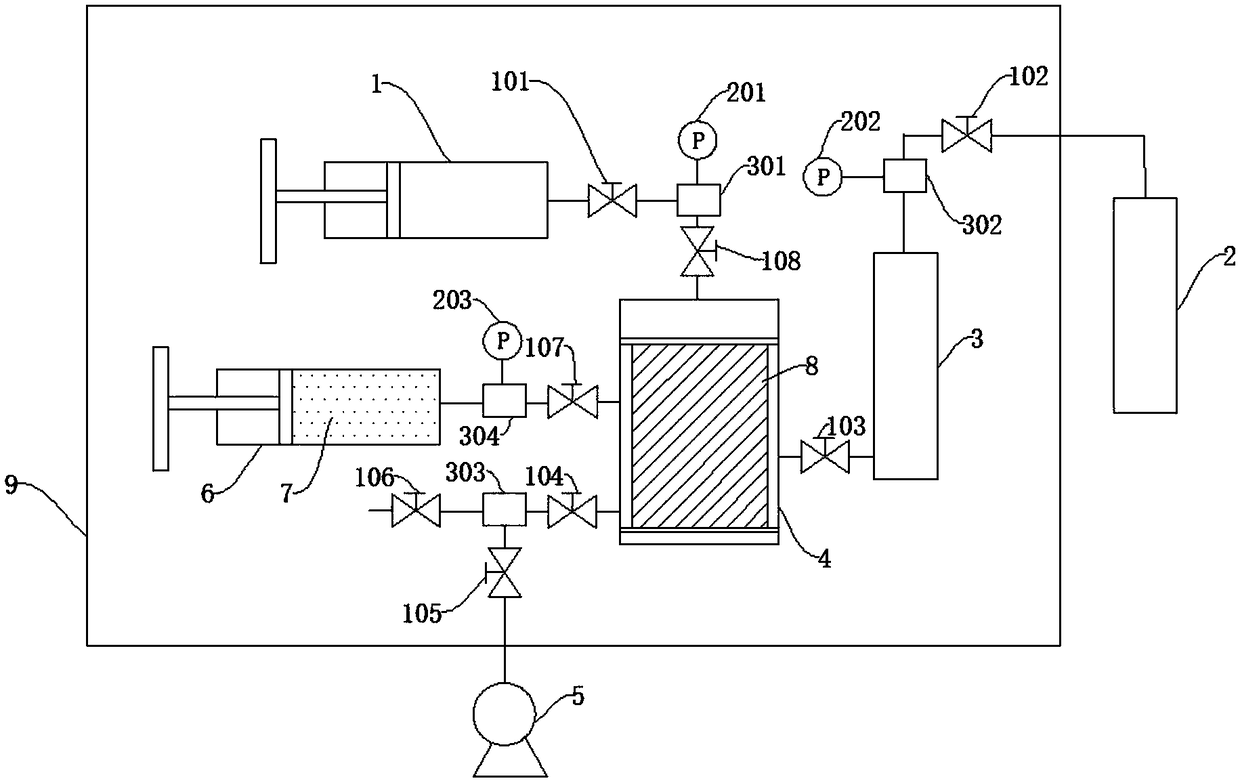
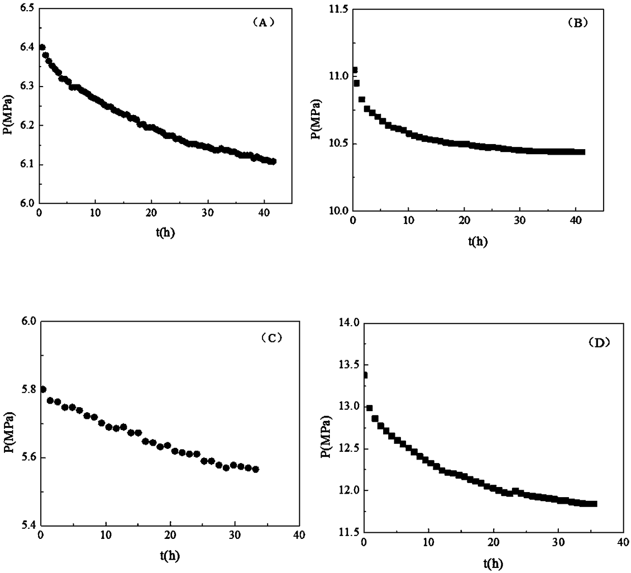
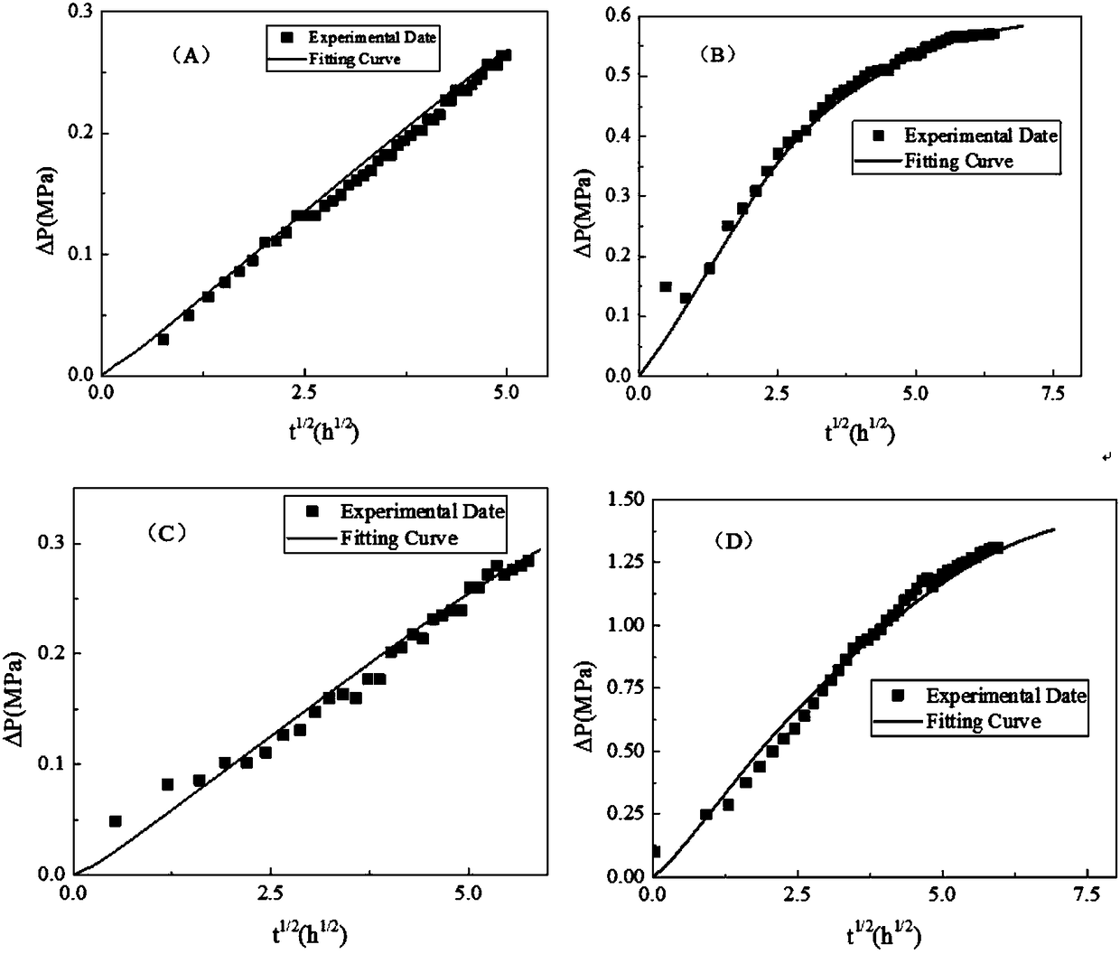
[0154] The thermostat 9 is set at a temperature of 60.0°C, and the core 8 sample, that is, shale I (see Table 1 for sample parameters) is placed in the radial core holder 4, the confining pressure is increased to 20 MPa, and after vacuuming and saturating the dodecane 7 , to CO 2 Inject a certain amount of CO into the high pressure vessel 3 2 Gas, maintain pressure 6.43MPa, CO 2 Inject the rock core 8 saturated with dodecane 7, and record the pressure change with time during the diffusion process through the second pressure sensor 202, such as figure 2 Shown in (A); through the calculation of this method, the obtained CO 2 The relevant parameters of the adsorption process are shown in Table 1, and the CO 2 The relevant parameters in the diffusion process of the shale core 8 are shown in Table 2. The curve of pressure changing with time calculated by this method is compared with the curve obtained from the experiment. image 3 (A), it can be seen that under this condition,...

Embodiment 2

[0156] The thermostat 9 is set at a temperature of 60.0°C, and the core 8 sample, that is, shale I (see Table 1 for sample parameters) is placed in the radial core holder 4, the confining pressure is increased to 20 MPa, and after vacuuming and saturating the dodecane 7 , to CO 2 Inject a certain amount of CO into the high pressure vessel 3 2 Gas, maintain pressure 11.05MPa, CO 2 Inject into the rock core saturated with dodecane 7, and record the pressure change with time during the diffusion process through the second pressure sensor 202, such as figure 2 Shown in (B); through the calculation of this method, the obtained CO 2 The relevant parameters of the adsorption process are shown in Table 2, and the CO 2 The relevant parameters in the diffusion process of the shale core 8 are shown in Table 3. The curve of pressure changing with time calculated by this method is compared with the curve obtained from the experiment. image 3 (B), it can be seen that under this condit...

Embodiment 3

[0158] Set the temperature of the thermostat 9 at 60.0°C, put the sample of the core 8, that is, shale II (see Table 1 for sample parameters) into the radial core holder 4, increase the confining pressure to 20 MPa, and then vacuumize and saturate the dodecane 7 , to CO 2 Inject a certain amount of CO into the high pressure vessel 3 2 Gas, maintain pressure 5.80MPa, CO 2 Inject into the rock core saturated with dodecane 7, and record the pressure change with time during the diffusion process through the second pressure sensor 202, such as figure 2 Shown in (C); through the calculation of this method, the obtained CO 2 The relevant parameters of the adsorption process are shown in Table 2, and the CO 2 The relevant parameters in the diffusion process of the shale core 8 are shown in Table 3. The curve of pressure changing with time calculated by this method is compared with the curve obtained from the experiment. image 3 (C), it can be seen that under this condition, CO ...


PUM

PropertyMeasurementUnit
Volumeaaaaaaaaaa
Diameteraaaaaaaaaa
Diffusion coefficientaaaaaaaaaa

Abstract

The invention discloses an apparatus for measuring a diffusion coefficient during a shale oil carbon dioxide huffing-puffing process and a method thereof. According to the invention, a radial rock core holding unit, a confining pressure pump and a first pressure transducer are connected with a first three-way connector, a simulation oil saturation pump, a third pressure transducer and the radial rock core holding unit are connected with a fourth three-way connector, the radial rock core holding unit and a vacuum pump are communicated with outside through a third three-way connector, the radialrock core holding unit and a CO2 high-pressure container are connected, the CO2 high-pressure container, a second pressure transducer, and a CO2 gas tank are connected with a second three-way connector, and the confining pressure pump, the CO2 high-pressure container, the radial rock core holding unit, the simulation oil saturation pump, the first pressure transducer, the second pressure transducer, the third pressure transducer, the first three-way connector, the second three-way connector, the third three-way connector, and the fourth three-way connector are capable of controlling the temperature through a thermotank. The CO2 adsorption dissolving by shale and diffusion coefficient under crude oil expansion condition are considered, so that the apparatus and the method have important guidance meaning for designing an on-site exploitation scheme.

Description

technical field [0001] The invention relates to the field of petroleum engineering, in particular to a device and a method for measuring the diffusion coefficient of shale oil carbon dioxide huff and puff. Background technique [0002] With the continuous development and consumption of conventional oil and gas resources, the world petroleum industry is making a leap from conventional oil and gas to unconventional oil and gas. Unconventional oil and gas are mainly shale system oil and gas, including tight oil and gas, shale oil and gas. Tight oil and gas are oil and gas stored in reservoirs such as tight sandstone or limestone, and the oil and gas have experienced short-distance migration. Shale oil and gas refer to the oil and natural gas enriched in organic-rich black shale formations. The oil and gas have basically not experienced the migration process. At present, shale gas has become a hot spot in the exploration and development of unconventional natural gas in the worl...

Claims


Application Information

Patent Timeline
IPC IPC(8): G01N13/04
CPCG01N13/04G01N2013/003
Inventor 宫厚健朱超凡李亚军董明哲苏玉亮徐龙邹洪俊尚胜祥王宏前李子靳
Owner CHINA UNIV OF PETROLEUM (EAST CHINA)
Why Eureka
Try Eureka