Device and method capable of qualitatively and quantitatively analyzing residue in vacuum system

A vacuum system and quantitative analysis technology, which is applied to measurement devices, analytical materials, material separation, etc., can solve problems such as damage to the chromatographic sampling system, damage to chromatographic components, and inability to complete sample gas collection.

Pending Publication Date: 2018-08-03
苏州铭谱源分析仪器有限公司
View PDF11 Cites 1 Cited by
  • Summary
  • Abstract
  • Description
  • Claims
  • Application Information

AI Technical Summary

Problems solved by technology

It cannot be directly connected to the vacuum system, and the collection of sample gas cannot be completed under the negative pressure environment of the vacuum system
Further, the negative pressure environment may damage the chromatographic sampling system, and may also cause certain damage to the chromatographic components

Method used


Image

  • Device and method capable of qualitatively and quantitatively analyzing residue in vacuum system
  • Device and method capable of qualitatively and quantitatively analyzing residue in vacuum system
  • Device and method capable of qualitatively and quantitatively analyzing residue in vacuum system

Examples


no. 1 example

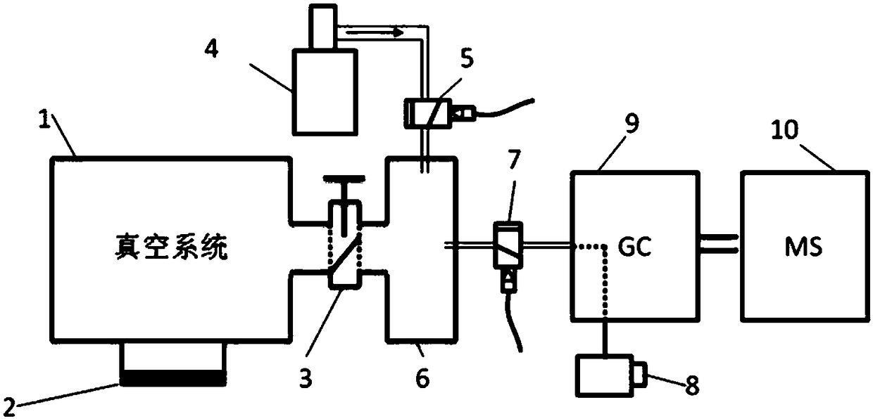
[0026] see figure 1 , figure 1 It is a structural schematic diagram of the present invention.

[0027] The present invention relates to a device and method for qualitative and quantitative analysis of residues in a vacuum system, comprising a vacuum system to be tested 1, a vacuum stop valve 2, first and second vacuum solenoid valves 5 and 7, a gas buffer chamber 6, and a gas source 4. Sampling pump 8, chromatograph 9 and mass spectrometer 10, the vacuum system 1 to be tested and the gas buffer chamber 6 are connected or cut off through the vacuum shut-off valve 3, and the gas source 4 and the gas buffer chamber 6 are connected through the first vacuum The solenoid valve 5 realizes the connection or cutoff of the gas, and the chromatograph 9 and the gas buffer chamber 6 are connected or cut off through the second vacuum solenoid valve 7 .

[0028] Further, the gas buffer chamber 6 is communicated with the quantitative loop 11 through the first three-way valve 15, and the qua...

no. 2 example

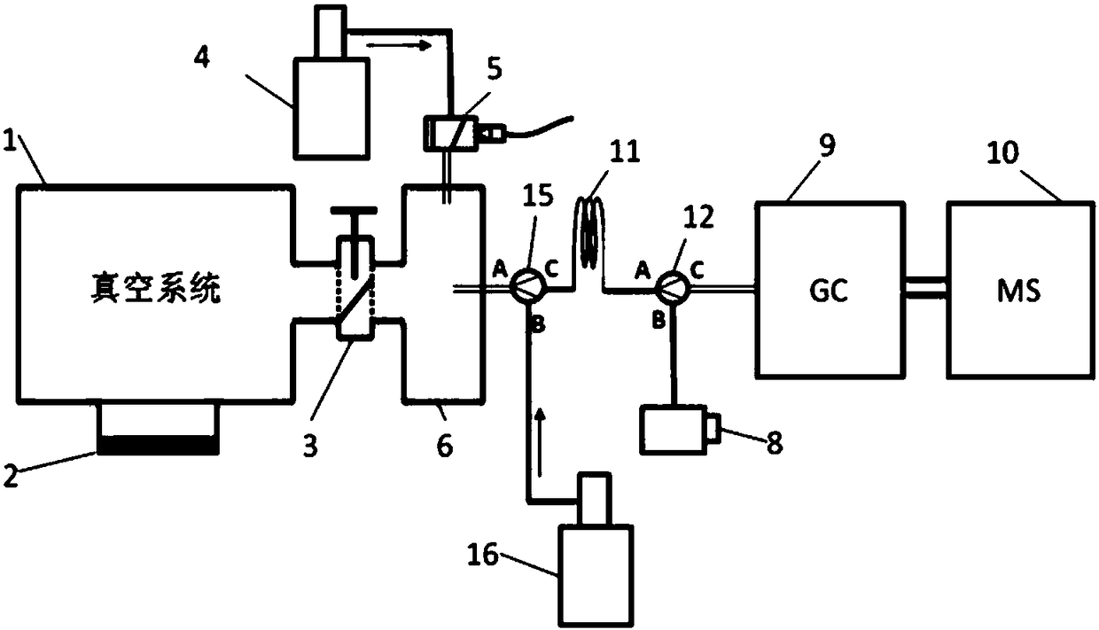
[0036] refer to figure 2 , figure 2 It is a schematic structural diagram of the second embodiment of the present invention;

[0037] Schematic diagram of a device for qualitative and quantitative analysis of complex residues in vacuum systems. The device consists of a vacuum system to be tested 1, a vacuum stop valve 3, a vacuum solenoid valve 5, a gas buffer chamber 6, the first and second gas sources 4 and 16, the first and second three-way valves 15 and 12, and a quantitative loop 11. , a sampling pump 8, a gas chromatograph 9 and a mass spectrometer 10. The vacuum shut-off valve 3 is used to connect the vacuum system 1 to be tested and the gas buffer chamber 6, and is used to control the communication and cut-off between the two; the vacuum solenoid valve 5 is used to connect the first gas source 4 and the gas buffer chamber chamber 6, and is used for on-off of the first gas; the first three-way valve 15 is used to connect the quantitative loop 11, the gas buffer cham...

no. 3 example

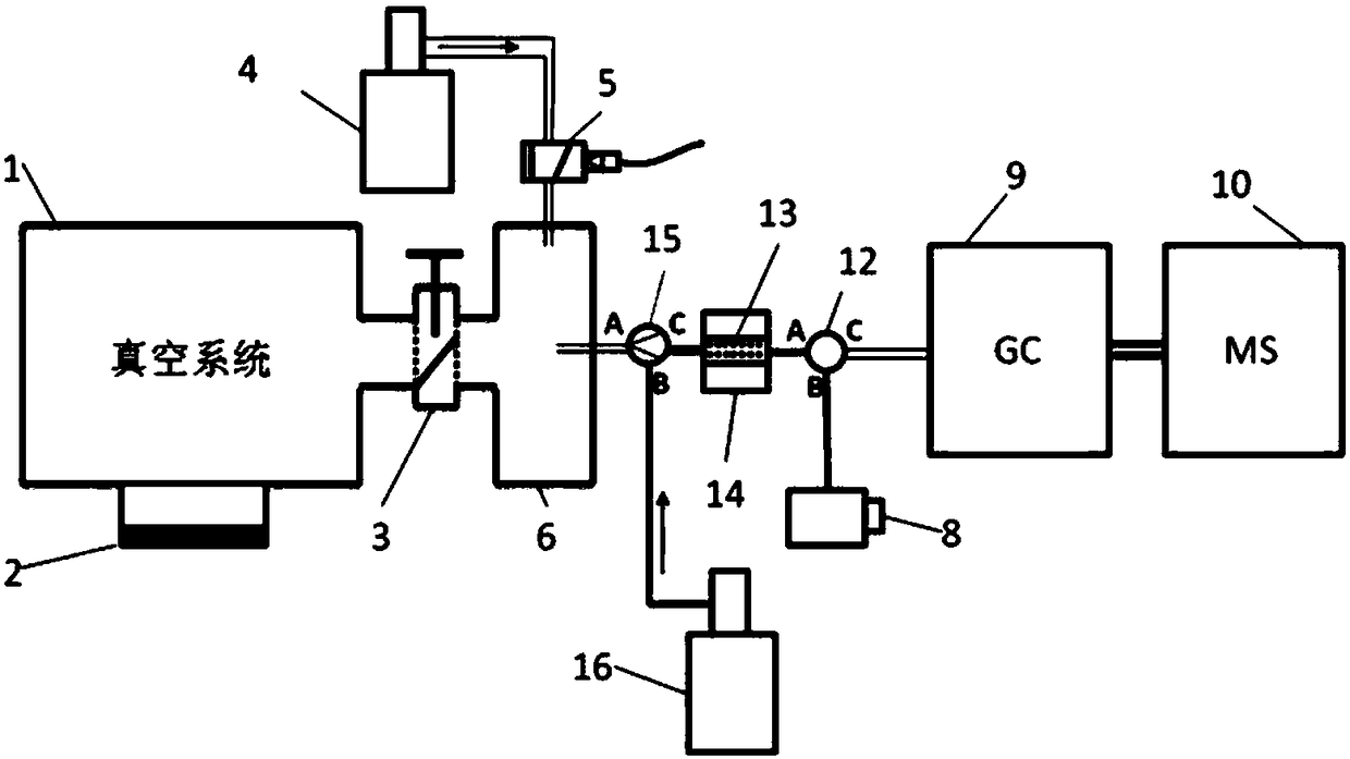
[0043] refer to image 3 , image 3 It is a structural schematic diagram of the third embodiment of the present invention.

[0044] Schematic diagram of a device for qualitative and quantitative analysis of complex residues in a vacuum system. The device consists of a vacuum system to be tested 1, a vacuum stop valve 3, a vacuum solenoid valve 5, a gas buffer chamber 6, the first and second gas sources 4 and 16, the first and second three-way valves 15 and 12, and the enricher 13. Composed of a sampling pump 8, a gas chromatograph 9 and a mass spectrometer 10. The vacuum shut-off valve 3 is used to connect the vacuum system 1 to be tested and the gas buffer chamber 6, and is used to control the communication and cut-off between the two; the vacuum solenoid valve 5 is used to connect the first gas source 4 and the gas buffer chamber The first three-way valve 15 is used to connect the enricher 13, the gas buffer chamber 6 and the second gas source 16, and is used to control t...


PUM


Abstract

The invention relates to the technical field of vacuum monitoring, in particular to a device and method capable of qualitatively and quantitatively analyzing a residue in a vacuum system. The device comprises a vacuum system to be detected, a vacuum stop valve, a first vacuum electromagnetic valve, a second vacuum electromagnetic valve, a gas buffer chamber, a gas source, a sampling pump, a chromatograph and a mass spectrometer, wherein communication or shutoff between the vacuum system to be detected and the gas buffer chamber is achieved through the vacuum stop valve; gas communication or gas shutoff between the gas source and the gas buffer chamber is achieved through the first vacuum electromagnetic valve; communication or shutoff between the chromatograph and the gas buffer chamber isachieved through the second vacuum electromagnetic valve. The device breaks through a great defect that in the existing residual gas analyzing mass spectrometry, an organic residue with complex components cannot be analyzed, so that an organic matter with the complex components can be accurately analyzed qualitatively and quantitatively. A standard sample experimental test shows that through thedevice and the method, a mixed gas containing 38 organic compounds in the vacuum system can be accurately analyzed qualitatively and quantitatively.

Description

technical field [0001] The invention relates to the technical field of vacuum monitoring, in particular to a device and method capable of qualitatively and quantitatively analyzing residues in a vacuum system. Background technique [0002] Vacuum systems play an important role in many fields, such as civil fields such as vacuum sputtering coating, mass spectrometry, and vacuum smelting, as well as high-tech fields such as space simulation, satellite environment simulation, large hadron collider, and synchrotron radiation. systems are essential. In practical applications, real-time monitoring of the vacuum system is required to evaluate the performance and status of the vacuum system. The main monitoring objective is to determine the composition and amount of residual gas in the vacuum system. Existing vacuum system residual gas analysis mainly adopts mass spectrometer residual gas analyzer, and its specific detection method is as follows: directly connect the vacuum system...

Claims


Application Information

Patent Timeline
Patent Type & Authority Applications(China)
IPC IPC(8): G01N30/02G01N30/72
CPCG01N30/02G01N30/72G01N2030/025
Inventor 李晓旭肖育
Owner 苏州铭谱源分析仪器有限公司
Why Eureka
Try Eureka