Supercharge Your Innovation With Domain-Expert AI Agents!

Aerated grit sand setting deslagging basin and sewage treatment system thereof

A sewage treatment system and aeration sand settling technology, which is applied in the direction of sedimentation tank, sedimentation tank, sedimentation separation, etc., can solve the problems such as wear of the sand suction end of the truss truck, inability to stop, tedious pump adjustment work, etc., to avoid corrosion and wear, Improve the service life and improve the effect of the working environment

Inactive Publication Date: 2018-08-14
青岛海安生物环保有限公司
View PDF0 Cites 0 Cited by
  • Summary
  • Abstract
  • Description
  • Claims
  • Application Information

AI Technical Summary

Problems solved by technology

In the prior art, the advection grit chamber is sucked back and forth by the truss truck. Since the height of the sand at the water inlet and outlet is different, if the truss truck with a fixed height is used, the sand-absorbing end of the truss truck will be worn; To avoid wear and tear, it is necessary to carry out tedious pump adjustment work
[0006] However, in operation, such frequent adjustments cannot actually be realized, so the sand particles at the outlet of the aerated grit chamber will accumulate more and more, and finally the slag can only be manually cleaned after the pond is emptied
On the one hand, it affects the operation of the equipment, on the other hand, due to the H in the sediment 2 S concentration is high and highly toxic, which is harmful to the health of slag cleaning workers
[0007] 2. The operation of the truss car and the slag scraping mechanism depends on the sensor
[0008] The working environment of the aerated grit chamber is humid and dirty, which sometimes causes the sensor to fail
For the girder truck, once the sensor fails, it will cause the girder truck to fail to stop when it reaches the pool end, and the wire will break, causing a short circuit or electric shock
For the existing lift-type slag scraping mechanism, if the sensor is damaged or blocked, it will not be able to lift and scrape slag

Method used


Image

  • Aerated grit sand setting deslagging basin and sewage treatment system thereof
  • Aerated grit sand setting deslagging basin and sewage treatment system thereof
  • Aerated grit sand setting deslagging basin and sewage treatment system thereof

Examples


Embodiment 1

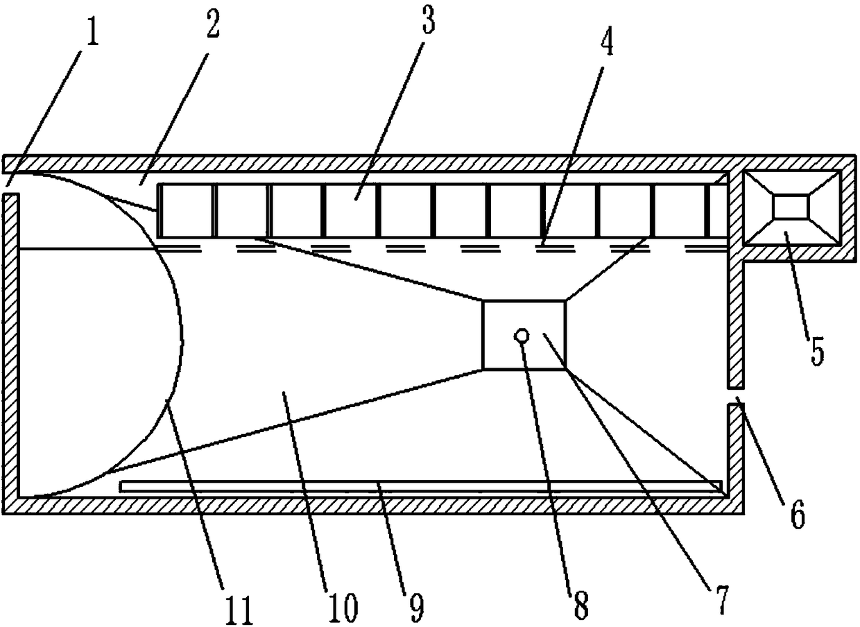
[0074] Such as Figure 1a and Figure 2-5 As shown, an aeration and deslagging tank includes a tank body, an aeration pipe 9, a first slag collecting structure 5 and a slag scraping mechanism 3, the tank body includes a water inlet 1 and a first water outlet 6, and the tank The bottom surface of the body includes an arc-shaped surface 13, a slope 14, and a sand collection area 7 from the water inlet to the water outlet. Sand suction pipe 8 is arranged, and sand suction pipe is connected with sand suction pump 31; The first water outlet is submerged weir.

[0075] It also includes a water distributor, the water distributor is combined with the arc surface to realize water distribution; the water distributor spans the width direction of the aeration sand settling and slag removal tank, and the water distributor consists of a water distribution plate 11 whose top is not lower than the water surface Composition, the water distribution plate includes a vertically arranged arc pane...

Embodiment 2

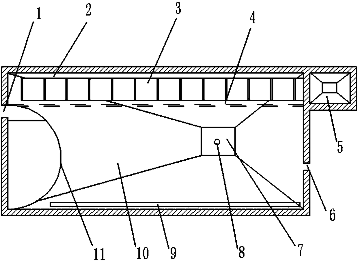
[0081] Such as Figure 1b and Figure 2-5 As shown, a kind of aerated sand sedimentation and slag removal tank includes a tank body, an aeration pipe, a first slag collecting structure and a slag scraping mechanism. The tank body includes a water inlet and a first water outlet. From the water end to the water outlet, it includes an arc surface, a slope and a sand collection area in turn. The sand collection area is surrounded by slopes that allow sand particles to gather in the sand collection area. The sand collection area is equipped with sand suction pipes. It is connected with the sand suction pump; the first water outlet is the overflow weir.

[0082] It also includes a water distributor, which is combined with the curved surface to realize water distribution; the water distributor spans the width direction of the aeration, sand, and slag removal tank, and the water distributor is composed of a water distribution board whose top is not lower than the water surface , the w...

Embodiment 3

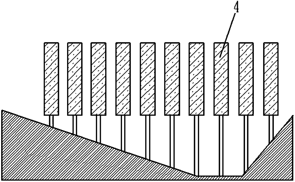
[0088] Such as Figure 6-8 As shown, a kind of aerated sand sedimentation and slag removal tank includes a tank body, an aeration pipe, a first slag collecting structure and a slag scraping mechanism. The tank body includes a water inlet and a first water outlet. From the water end to the water outlet, it includes an arc surface, a slope and a sand collection area in turn. The sand collection area is surrounded by slopes that allow sand particles to gather in the sand collection area. The sand collection area is equipped with sand suction pipes. Connected with the sand suction pump; the first water outlet can be an overflow weir.

[0089] It also includes a water distributor, which is combined with the curved surface to realize water distribution; the water distributor spans the width direction of the aeration, sand, and slag removal tank, and the water distributor is composed of a water distribution board whose top is not lower than the water surface , the water distribution...


PUM


Abstract

The invention relates to an aerated sand setting deslagging basin and a sewage treatment system thereof, and belongs to the technical field of sewage treatment. The aerated sand setting deslagging basin comprises a basin body, an aeration pipe, a first slag collecting structure and a slag scraping mechanism. The bottom surface of the basin body sequentially comprises an arc-shaped surface, a slopeand a sand collecting area from a water inlet end to a water outlet end, and also comprises a water distributor, a slag damming wall and the slag scraping mechanism. The sewage treatment system alsocomprises a spiral conveying machine, an air pump unit and a sand-water separator. The aerated sand setting deslagging basin and the sewage treatment system thereof provided by the invention are simple and convenient to operate, and cost-saving.

Description

technical field [0001] The invention relates to an aeration sand settling and slag removal tank and a sewage treatment system thereof, belonging to the technical field of sewage treatment. Background technique [0002] Sewage treatment usually needs to set up grit chambers in the pretreatment stage to ensure the normal operation of subsequent treatment facilities. There are three types of grit chambers: flat flow, vertical flow, and aerated. The advection type grit chamber is the most commonly used type of grit chamber, and its water flow part is actually a widened and deepened open channel, which has the advantages of simple structure, stable operation, good treatment effect and easy sand discharge; vertical flow type grit chamber The pool is a circular pool, its structure is relatively complicated, the treatment effect is generally poor, and it is not used much now; the aerated grit chamber is a long channel, which is to add an aeration tube to the conventional advection ...

Claims


Application Information

Patent Timeline
IPC IPC(8): B01D21/04B01D21/30B01D21/00
CPCB01D21/0006B01D21/003B01D21/0042B01D21/04B01D21/30
Inventor 姜晓华江安宋德安
Owner 青岛海安生物环保有限公司
Features
  • R&D
  • Intellectual Property
  • Life Sciences
  • Materials
  • Tech Scout
  • Unparalleled Data Quality
  • Higher Quality Content
  • 60% Fewer Hallucinations
Learn More