Rotor position detection device for brushless DC motor or AC permanent magnet synchronous motor

A technology of permanent magnet synchronous motor and DC brushless motor, which is applied in the direction of electromechanical devices, electronic commutators, electrical components, etc., and can solve the problem of large impact on the working environment, difficulty in readjusting the zero position of the sensor, and no redundant configuration of the sensor, etc. problems, achieve the effect of zero readjustment and improve system reliability

Inactive Publication Date: 2018-08-14
NORTHWESTERN POLYTECHNICAL UNIV
View PDF5 Cites 7 Cited by
  • Summary
  • Abstract
  • Description
  • Claims
  • Application Information

AI Technical Summary

Problems solved by technology

[0007] In summary, the current technical problems specifically include: a) there is no detection device that can output the level signal and angular position signal of the rotor position at the same time, and at the same time meet the commutation control requirements of brushless DC motors or permanent magnet synchronous motors; b) the sensor Without redundant configuration, the system cannot work normally once it fails; c) The sensor is usually integrated inside the motor, which is greatly affected by the internal working environment of the motor, and once the motor is processed, the zero position of the sensor is difficult to readjust

Method used


Image

  • Rotor position detection device for brushless DC motor or AC permanent magnet synchronous motor
  • Rotor position detection device for brushless DC motor or AC permanent magnet synchronous motor
  • Rotor position detection device for brushless DC motor or AC permanent magnet synchronous motor

Examples


Embodiment Construction

[0022] The present invention will be further described below with reference to specific embodiments. The exemplary embodiments and descriptions of the present invention are used to explain the present invention, but are not intended to limit the present invention.

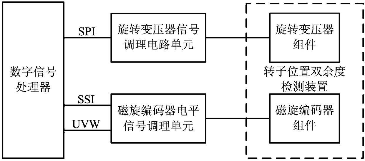
[0023] like figure 1 As shown, a device for detecting the rotor position of a DC brushless motor or an AC permanent magnet synchronous motor in this embodiment includes a rotor angular position double redundancy detection device arranged outside the DC brushless motor or AC permanent magnet synchronous motor, and a rotor angular position detection device and a rotor. A resolver signal conditioning circuit unit and a magnetic rotary encoder level signal conditioning unit connected to the angular position double redundancy detection device, and a digital signal processor connected with the resolver signal conditioning circuit unit and the magnetic rotary encoder level signal conditioning unit The rotor position doubl...


PUM


Abstract

The invention discloses a rotor position detection device for a brushless DC motor or an AC permanent magnet synchronous motor. The device comprises a rotor angle position double-redundancy detectiondevice arranged outside the brushless DC motor or the AC permanent magnet synchronous motor, a rotary transformer signal conditioning circuit unit and a magnetic-rotation encoder level signal conditioning unit which are connected to the rotor angle position double-redundancy detection device, and a digital signal processor connected to the rotary transformer signal conditioning circuit unit and the magnetic-rotation encoder level signal conditioning unit, wherein the rotor position double-redundancy detection device is formed by a rotary transformer assembly and a magnetic rotation encoder assembly. Compared with the prior art, the requirements for rotor position detection of the brushless DC motor and the AC permanent magnet synchronous motor can be met at the same time, and meanwhile, the device has a commutation level signal of the brushless DC motor and a high-precision angle position resolution and zero-position re-adjustment capability. A system can still obtain the correct rotorangle under a condition of sensor failure, so that the reliability of the system is improved.

Description

technical field [0001] The invention relates to the field of servo motor rotor position detection devices, in particular to a rotor position detection device of a DC brushless motor or an AC permanent magnet synchronous motor. Background technique [0002] In the field of electric actuators, DC brushless motors and AC permanent magnet synchronous motors have been widely used. The control systems of these two types of servo motors use electronic commutation devices to commutate the winding current, so the relative position of the rotor relative to the stator winding must be obtained, which is usually detected by an angle sensor. [0003] The brushless DC motor in the three-phase six-state mode senses the position of the rotor through three Hall elements evenly distributed on the end face of the motor stator, and provides six level combinations in one electrical cycle, corresponding to different commutation The signal is used to control the turn-on and turn-off of the three-p...

Claims


Application Information

Patent Timeline
Patent Type & Authority Applications(China)
IPC IPC(8): H02P6/16H02K29/06H02K29/08H02K11/21H02K11/215
CPCH02P6/16H02K11/21H02K11/215H02K29/06H02K29/08
Inventor 李朋周军高智刚张佼龙
Owner NORTHWESTERN POLYTECHNICAL UNIV
Why Eureka
Try Eureka