Robot laser welding and grinding device

A technology of laser welding and robots, which is applied in the direction of manipulators, program-controlled manipulators, manufacturing tools, etc., can solve problems such as broken workpieces, damage, rough and uneven product surfaces, etc., to avoid collisions and ensure product quality.

Pending Publication Date: 2018-08-17
芜湖鲍斯柯机器人股份有限公司
View PDF0 Cites 2 Cited by
  • Summary
  • Abstract
  • Description
  • Claims
  • Application Information

AI Technical Summary

Problems solved by technology

At present, the deburring processing of castings, plastic parts, steel products and other material workpieces of most domestic manufacturers is mostly done manually, or using hand-held pneumatic or electric tools for grinding, grinding, filing, etc., which will easily lead to product defect rate. Rising, low efficiency, rough and uneven surface of processed products, etc. Some manufacturers have also begun to use robots to install electric or pneumatic tools for automatic grinding
Compared with hand-held grinding, robot deburring products can effectively improve production efficiency, reduce costs, and improve product yield. However, due to other factors such as the rigidity of the mechanical arm, positioning errors, etc., the use of robots to clamp electric and pneumatic product deburring is aimed at irregular burrs. It is easy to break the knife or cause damage to the workpiece; the weld seam after laser welding still has defects such as spatter, welding slag, and low surface accuracy, and the weld seam still needs to be polished
The existing grinding equipment (domestic) can also be installed on the robot arm, and there is no corresponding design for the laser welding and grinding environment, so it cannot meet the requirements

Method used


Image

  • Robot laser welding and grinding device

Examples


Embodiment Construction

[0020] In order to deepen the understanding of the present invention, the present invention will be further described below in conjunction with examples, which are only used to explain the present invention and do not constitute a limitation to the protection scope of the present invention.

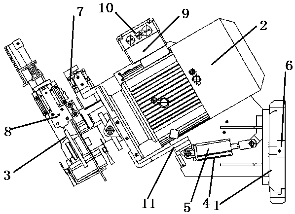
[0021] Such as figure 1 As shown, this embodiment provides a robot laser welding and grinding device, which includes a grinding execution part, a power adjustment part and a fixed support base 1, the power adjustment part is arranged on the fixed support base 1, and the grinding execution part is set At the front end of the power adjustment part, the grinding execution part includes a motor 2 and a grinding wheel sheet 3. The grinding wheel sheet 3 is installed at the front end of the motor 2. The power adjustment part includes a cylinder 4 and a solenoid valve 5. The motor 2 is arranged on the cylinder 4, the other end of the cylinder 4 is connected to the fixed support base 1, and the e...


PUM


Abstract

The invention provides a robot laser welding and grinding device comprising a grinding execution part, a force regulating part and a fixed support base. The force regulating part is arranged on the fixed support base, and the grinding execution part is arranged at the front end of the force regulating part; the grinding execution part comprises a motor and a grinding disk installed at the front end of the motor, and the force regulating part comprises a cylinder and a solenoid valve; and the motor is arranged at one end of the cylinder of which the other end is connected to the fixed support base, and the solenoid valve is arranged on the cylinder. The advantages of mechanical and electronic integration are fully utilized, and the control over the mechanical execution part is achieved through programming of corresponding control procedures while different feedbacks are arranged rationally. If the control is proper, proper grinding of a weld joint can be ensured, and the ground surfaceroughness is no more than 1.6 [mu]m; and base metal is not damaged. One grinding disk can be used for grinding at least 300 finished vehicles, and the length of each weld joint is ensured to be 2.0 m.

Description

technical field [0001] The invention relates to the field of laser welding, in particular to a robot laser welding and grinding device. Background technique [0002] Laser welding is an efficient and precise welding method that uses a high-energy-density laser beam as a heat source. Laser welding is one of the important aspects of the application of laser material processing technology. In the 1970s, it was mainly used for welding thin-walled materials and low-speed welding. The welding process is heat conduction, that is, the laser radiation heats the surface of the workpiece, and the surface heat diffuses to the inside through heat conduction. By controlling the width, energy, peak power and repetition frequency of the laser pulse and other parameters to melt the workpiece and form a specific molten pool. Due to its unique advantages, it has been successfully applied in the precision welding of micro and small parts. In modern industry, it is often used to control the l...

Claims


Application Information

Patent Timeline
Patent Type & Authority Applications(China)
IPC IPC(8): B25J11/00B25J9/16
CPCB25J11/0065B25J9/1633
Inventor 曹杰芮定文李若涵
Owner 芜湖鲍斯柯机器人股份有限公司
Why Eureka
Try Eureka