Laser cladding method, laser head, laser and cladding system for realizing laser cladding method

A laser cladding and laser technology, applied in metal material coating process, coating, etc., can solve the problems of inability to real-time on-line heat treatment, high heat input, deformation performance, etc., to improve laser processing efficiency, high degree of automation, Effect of Reducing Residual Stress

Pending Publication Date: 2018-08-17
XIAN BESAME LASER TECH CO LTD
View PDF6 Cites 13 Cited by
  • Summary
  • Abstract
  • Description
  • Claims
  • Application Information

AI Technical Summary

Problems solved by technology

[0007] The purpose of the present invention is to provide a laser cladding method to realize the problem that the existing laser cladding method for preheating the workpiece substrate

Method used


Image

  • Laser cladding method, laser head, laser and cladding system for realizing laser cladding method
  • Laser cladding method, laser head, laser and cladding system for realizing laser cladding method

Examples


Embodiment 1

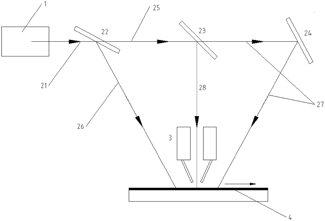
[0054] Such as figure 1 A laser cladding system shown includes a powder feeder 3 and a laser cladding laser. The laser cladding laser includes a laser body 1 and a laser head; the laser body 1 is a high-power semiconductor stack laser.

[0055] The laser head includes a first beam splitter 22, a second beam splitter 23 and a reflection mirror 24 arranged in sequence along the outgoing direction of the laser beam 21; the first beam splitter 22 and the second beam splitter 23 are flat beam splitters ; Mirror 24 is a plane mirror.

[0056] The first beam splitter 22 is used to divide the outgoing laser light 21 into the first transmitted laser light 25 and the first reflected preheating laser light 26; the second beam splitter 23 is used to divide the first transmitted laser light 25 into the second transmitted post-processing laser light 27 and the second reflection cladding laser 28; mirror 24 is used to change the direction of the second transmission post-processing laser 27; t...

Embodiment 2

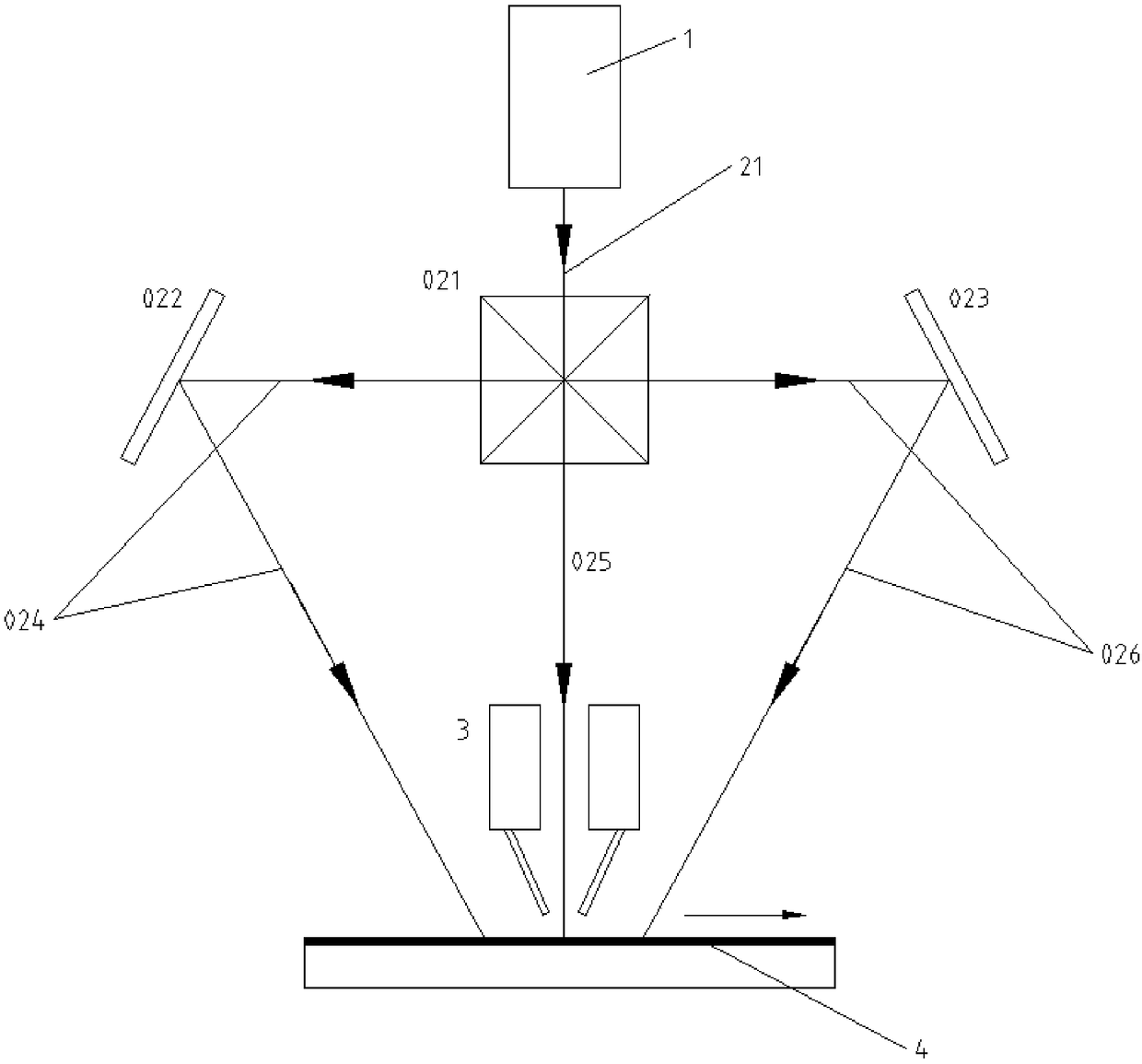
[0058] Such as figure 2 A laser cladding system shown includes a powder feeder 3 and a laser cladding laser. The laser cladding laser includes a laser body and a laser head; the laser body 1 is a high-power semiconductor stack laser.

[0059] The laser head includes a dichroic prism 021 arranged along the outgoing direction of the outgoing laser light 21, and a first mirror 022 and a second reflective mirror 023 arranged on both sides of the dichroic prism 021; the dichroic prism 021 divides the outgoing laser light 21 into prism preheating laser 024, prism cladding laser 025 and prism post-processing laser 026; prism cladding laser 025 directly irradiates the workpiece 4 to be processed along the exit direction of the outgoing laser 21; prism preheating laser 024 is reflected by the first reflector 022 and irradiates the workpiece to be processed 4. The prism post-processing laser 026 is reflected by the second reflector 023 and irradiates the workpiece 4 to be processed.


PUM


Abstract

The invention relates to the technical field of laser cladding, and provides a laser cladding method, and a laser head, a laser and a cladding system for realizing the laser cladding method aiming atthe problems of deformation and performance degradation due to the fact that an existing method of laser cladding preheating on a machined workpiece base body cannot realize real-time online heat treatment and high heating input for preheating. The laser cladding method comprises the following steps that 1, outgoing lasers of the laser are divided into preheating lasers, cladding lasers and post-processing lasers; 2, the preheating lasers are irradiated on a workpiece to be processed, and the workpiece is preheated; 3, the cladding lasers are irradiated on the preheated workpiece to be processed to form a molten pool, and at the same time, alloy powder is blown into the molten pool formed on the surface of the workpiece to be processed; and 4, the post-processing lasers are irradiated on acladding layer after cladding, and post-annealing treatment is carried out on the cladding layer.

Description

technical field [0001] The invention relates to the technical field of laser cladding, in particular to a laser cladding method, a laser head for realizing the method, a laser and a cladding system. Background technique [0002] Laser cladding technology is an advanced manufacturing technology combining laser technology and processing technology, which has developed rapidly in recent years. As an advanced surface modification technology, it is widely used in the surface modification of materials and the repair of failed parts, which solves many problems in engineering practice and creates huge economic benefits in engineering practice. [0003] Since the laser cladding process is a process of rapid heating and rapid cooling, the solidification speed of the molten pool is fast, the temperature gradient is high, and the thermal stress generated is high. Therefore, the material is easy to crack, especially when the hardness of the cladding material is high, the crack problem i...

Claims


Application Information

Patent Timeline
IPC IPC(8): C23C24/10
CPCC23C24/103
Inventor 王晓飚汤波李欣张国超杨英滔
Owner XIAN BESAME LASER TECH CO LTD
Why Eureka
Try Eureka