Non-cooperative short-wave radiation source wide-area distributed short-wave network single-antenna time difference positioning method

A short-wave radiation and time-difference positioning technology, which is applied in the direction of re-radiation, radio wave measurement systems, instruments, etc., can solve the problems of complex technology, illegal short-wave signal positioning, large investment, etc., to ensure national security and ensure short-wave electromagnetic Space security and the effect of improving positioning accuracy

Inactive Publication Date: 2018-08-17
WUHAN UNIV
View PDF9 Cites 9 Cited by
  • Summary
  • Abstract
  • Description
  • Claims
  • Application Information

AI Technical Summary

Problems solved by technology

[0004] A non-cooperative short-wave radiation source wide-area distributed short-wave network single-antenna time difference positioning method proposed by the present invention can be used to solve the positioning problem of illegal short-wave signals. It is a new short-wave positioning method, and its core is to break the traditional Based on the large investment and complex technology of array direction finding and intersection positioning, it is only necessary to use the existing equipment of the existing short-wave network and combine the ionospheric detection data and signal processing technology to realize the rapid discovery and detection of short-wave non-cooperative signals. Automatic positioning, and a breakthrough in improving positioning accuracy and greatly reducing positioning costs

Method used


Image

  • Non-cooperative short-wave radiation source wide-area distributed short-wave network single-antenna time difference positioning method
  • Non-cooperative short-wave radiation source wide-area distributed short-wave network single-antenna time difference positioning method
  • Non-cooperative short-wave radiation source wide-area distributed short-wave network single-antenna time difference positioning method

Examples


Embodiment

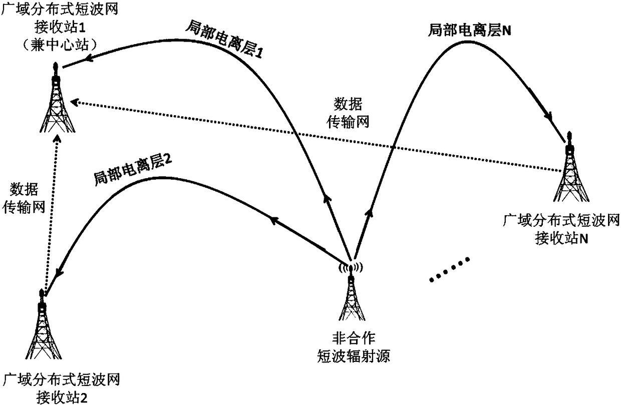
[0054] figure 1 As shown, based on the receiving stations of the wide-area distributed short-wave network, the sky-wave propagation signal of the short-wave radiation source is collected, and after being compressed locally, it is transmitted to the server of the master station of the wide-area distributed short-wave network. Each time difference of the receiving station, and then according to the geographical distribution of each receiving station, ionospheric parameters and time difference, the positioning result is optimized. In the present invention, since each receiving station in the short wave network needs to be completely synchronized in time and simultaneously collect signals of the same frequency, other processing is carried out by algorithmic software at the back end for digital signal processing.

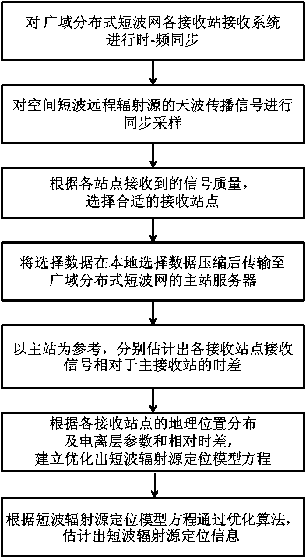
[0055] figure 2 As shown, a kind of non-cooperative shortwave radiation source wide-area distributed shortwave network single-antenna time difference positioning metho...


PUM


Abstract

The invention relates to a non-cooperative short-wave radiation source wide-area distributed short-wave network single-antenna time difference positioning method. The method provided by the inventioncomprises the steps that a sky-wave propagation signal of a short-wave radiation source is collected, and a suitable receiving station is selected; the collected data are locally compressed and transmitted to a wide-area distributed short-wave network main station server; a main station is used as for reference to estimate the time difference of each receiving station relative to a main receivingstation; and finally, a positioning result is optimized according to the geographical distribution of each receiving station and the ionospheric height parameter and time difference. According to theinvention, the method is based on a single short-wave receiving antenna and a single-channel receiver of each station in the existing wide-area distributed short-wave network; short-wave radiation source positioning is realized by using the time difference generated by the short-wave sky-wave propagation signal which reaches each receiving station through different paths; rebuilding a large receiving station is not needed, which saves a lot of manpower and funds; and the method has important promotion and application values in both civil short-wave radio management and short-wave military technical investigation.

Description

technical field [0001] The invention belongs to the technical field of positioning of short-wave radio radiation sources, and in particular relates to a single-antenna time-difference positioning method of a non-cooperative short-wave radiation source in a wide-area distributed short-wave network. Background technique [0002] Short-wave electromagnetic waves are widely used in the fields of short-wave communication, broadcasting and radar due to the long distance of action due to the refraction effect of the ionosphere, and are playing an increasingly important role in the fields of national economy, political diplomacy, national security, commerce and modern military. . However, after long-term development of short-wave radio technology, its spectrum utilization is extremely crowded. Not only that, driven by interests, some units or individuals arbitrarily use short-wave frequencies that are not allowed by the state to engage in radio services, causing interference to the...

Claims


Application Information

Patent Timeline
Patent Type & Authority Applications(China)
IPC IPC(8): G01S11/02
CPCG01S11/02
Inventor 高火涛高可至
Owner WUHAN UNIV
Why Eureka
Try Eureka