Metal plate stamping electric box
A sheet metal and electrical box technology, applied in the field of new energy vehicles, can solve problems such as reduced production capacity and efficiency, supply that is difficult to mass produce, and large welding deformation, so as to improve the overall structural strength, prevent rainwater from entering, and airtight Good results
- Summary
- Abstract
- Description
- Claims
- Application Information
AI Technical Summary
Problems solved by technology
Method used
Image


Examples
Embodiment 1
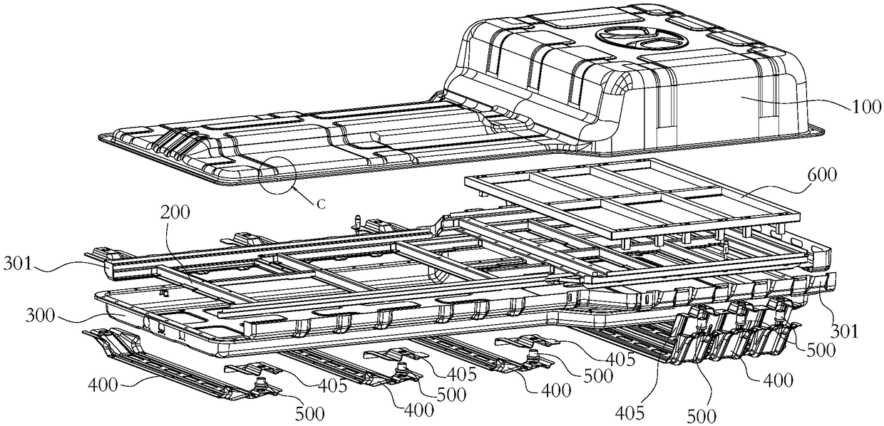
[0051] like Figure 1-Figure 14 As shown, this embodiment discloses a sheet metal stamping electric box, which is installed at the bottom of an electric vehicle; it includes a top cover 100, several module fixing beams 200 for installing battery modules, and a bottom case 300. The top cover 100 and the bottom case 300 are integrally formed by sheet metal stamping, and the module fixing beam 200 is formed by bending; the upper cover 100 is detachably connected to the bottom case 300 and forms a In the installation space for accommodating the battery module, the module fixing beam 200 is located in the installation space and welded and fixed with the bottom case 300 .
[0052] A specific scheme of the module fixing beam of this embodiment is as follows: Figure 11-Figure 14 As shown, the module fixing beam 200 is a ladder structure, and each step of the ladder structure 201 is arranged along the length direction of the module fixing beam 200; the step surfaces at both ends of t...
Embodiment 2
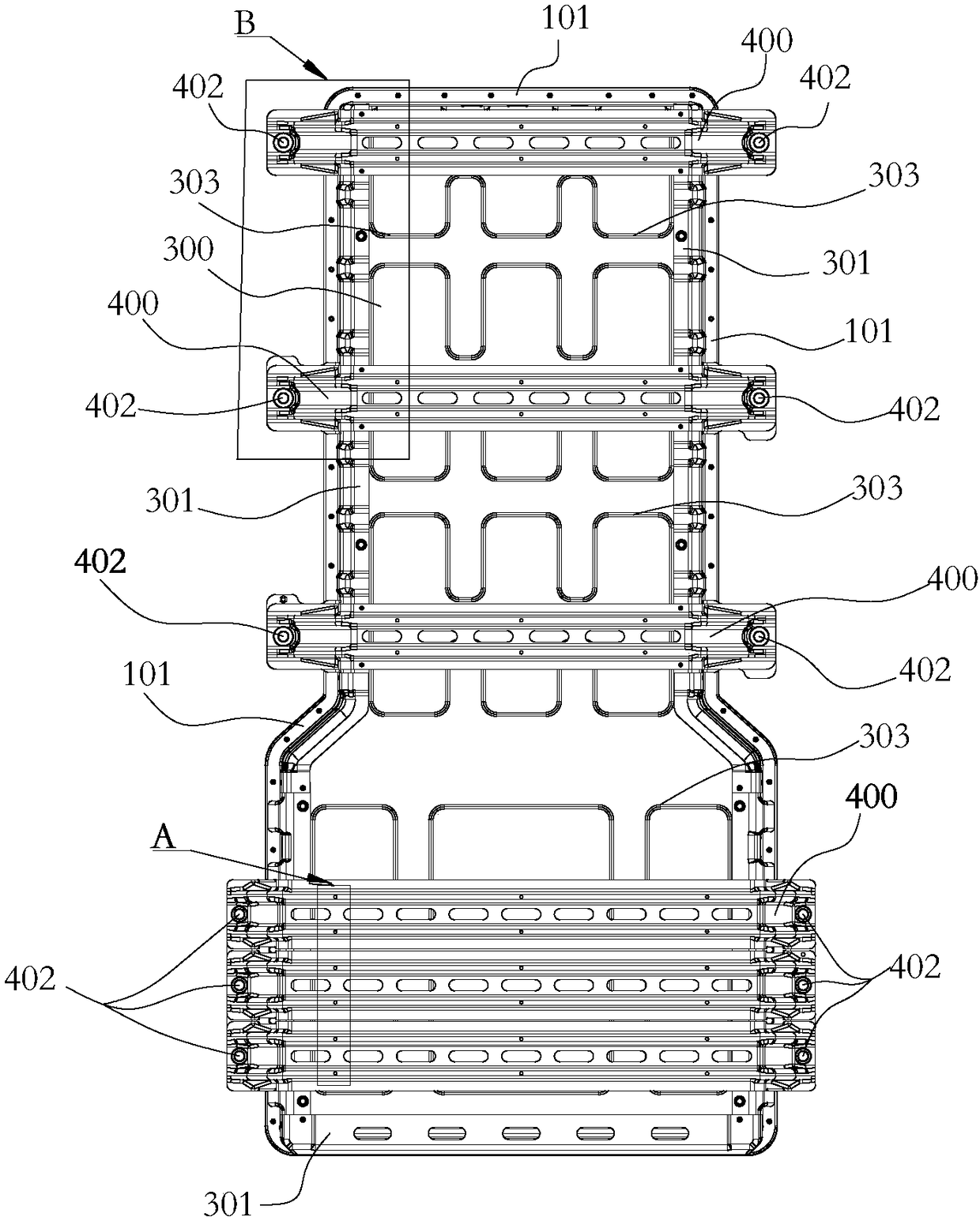
[0058] like Figure 1-Figure 10 As shown, in addition to the technical features of Embodiment 1, the sheet metal stamping electric box of this embodiment also includes a support beam 400, which is welded on the bottom surface of the bottom case 300 and extends out of the A part of the bottom shell 300, the two ends of the support beam 400 are respectively welded with guide sleeves 500, the support beam 400 is detachably connected with the electric vehicle through the guide sleeves 500 to support and install the sheet metal stamping electrical box The bottom of the electric car. The guide sleeve 500 is made by CNC machining with high precision, the thickness of the guide sleeve is 5mm, and the mechanical strength and shear resistance are high, so as to connect the electric box and the electric vehicle with high reliability. In this embodiment, the position of the lifting point of the support beam and the bottom of the electric vehicle are bolted through a guide sleeve, and the...
Embodiment 3
[0065] In addition to the technical features of Embodiment 2, the sheet metal stamping electric box of this embodiment is also equipped with several joists 301 adapted and welded on the edges around the bottom of the bottom shell 300, and the support beams 400 are welded to the joists 301 fixed; the bottom shell 300 is punched and formed with a first limiting portion 302 extending downward, and the joist 301 is punched and formed with a first punching hole adapted to the first limiting portion 302; the The first limiting part 302 snaps into the first punching hole to realize the limit of the joist 301 on the edge of the bottom shell 300; the first limiting part 302 is actually a limiting post formed by stamping downward on the bottom shell; The joist 301 is stamped and formed with a second limiting portion 410 extending downward, and the second limiting portion 410 is also a limiting column stamped and formed on the joist; the support beam 400 is stamped and formed with the fir...
PUM
 Abstract
Description
Claims
Application Information
 - R&D
- Intellectual Property
- Life Sciences
- Materials
- Tech Scout
- Unparalleled Data Quality
- Higher Quality Content
- 60% Fewer Hallucinations
Browse by: Latest US Patents, China's latest patents, Technical Efficacy Thesaurus, Application Domain, Technology Topic, Popular Technical Reports.
© 2025 PatSnap. All rights reserved.Legal|Privacy policy|Modern Slavery Act Transparency Statement|Sitemap|About US| Contact US: help@patsnap.com