Drafting roller for special polyethylene fibers, drafting machine and drafting device

A polyethylene fiber and drafting roller technology, which is applied in the fields of drafting rollers, drafting machines and drafting devices, can solve the problems of volatilization of extractant to the production workshop and unstable quality of primary fibers, so as to reduce the number of labor and labor Strength, improving the yield and quality of products, and reducing energy consumption

Pending Publication Date: 2018-08-21
河北和泰航天科技有限公司 +1
View PDF7 Cites 2 Cited by
  • Summary
  • Abstract
  • Description
  • Claims
  • Application Information

AI Technical Summary

Problems solved by technology

[0005] The purpose of the present invention is to provide a drafting roller, a drafting machine and a drafting device for special polyethylene fibers, so as to solve the problems of unstable raw fiber quality and extraction agent volatilization to the production workshop

Method used


Image

  • Drafting roller for special polyethylene fibers, drafting machine and drafting device
  • Drafting roller for special polyethylene fibers, drafting machine and drafting device
  • Drafting roller for special polyethylene fibers, drafting machine and drafting device

Examples


Embodiment 1

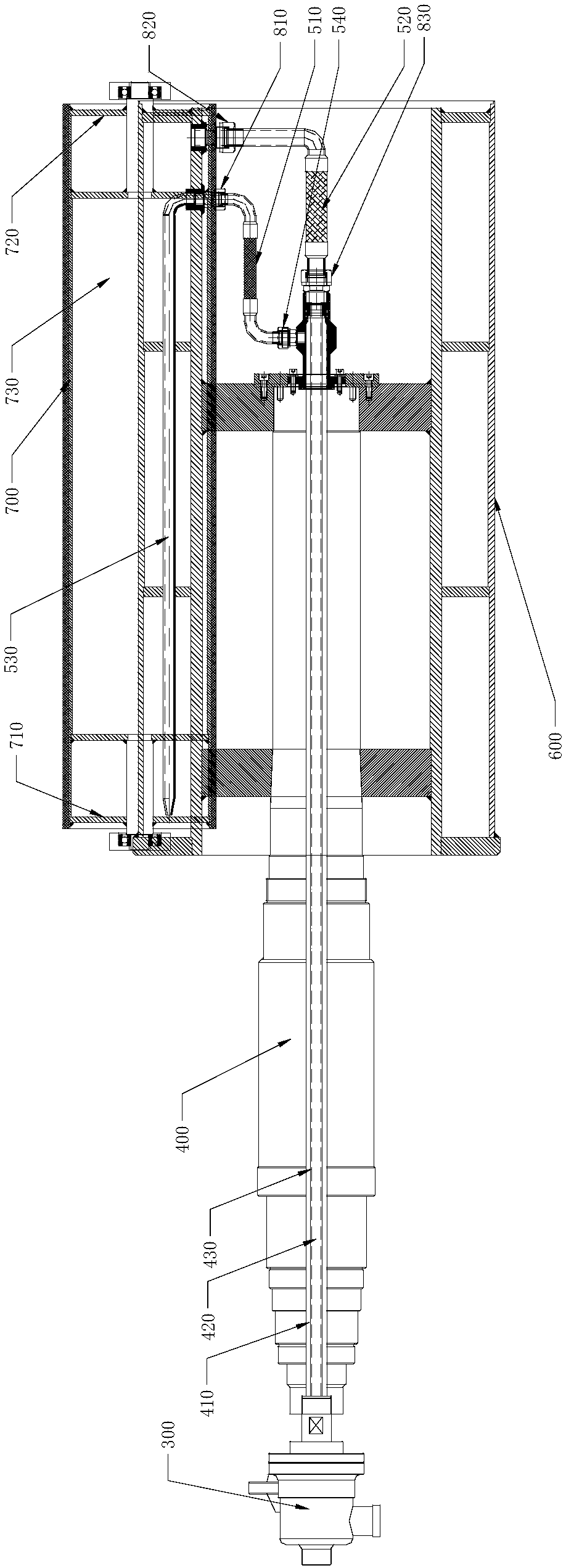
[0039] On the one hand, this embodiment provides a drafting roll for special polyethylene fibers, see figure 1 , Which includes a rotating shaft 400, a roller body 600, a jacketed roller 700 and a heat conducting medium tube, in which:

[0040] The rotating shaft 400 is provided with a first channel 410 and a second channel 420. The first channel 410 is cylindrical, and the second channel 420 is a circular cylindrical cross section. The axis of the first channel 410 and the second channel 420 The axes of both coincide with the axis of the rotating shaft 400. The independent first channel 410 and the second channel 420 provide an inlet and a return channel for the heat transfer medium, and the first channel 410, the second channel 420, and the rotating shaft 400 The axes of the three are coincident, so that the first channel 410 and the cross-sectional shape of the second channel 420 remain fixed when the three are rotated synchronously, which provides conditions for docking the pi...

Embodiment 2

[0059] On the basis of Example 1, the inventor found that since the outlet of the first channel 410 and the inlet of the second channel 420 are located at the same end of the rotating shaft 400, the horizontal position between the two is relatively small, such as when the medium flows directly. The same end of the cavity 430 is provided with a medium inlet and a medium outlet so that the left side of the medium inlet (such as figure 1 The fluidity of the heat transfer medium in the middle left direction is the left side) is very small, resulting in uneven temperature in the medium flow cavity 430. Therefore, the medium pipe 530 is fixed in the acrobatic medium flow cavity 430, and the first end of the medium pipe 530 is connected to Medium inlet, the second end of the medium conduit 530 extends to the first end 710 of the medium flow chamber 430 and is spaced from the end cap of the first end 710. The medium inlet and the medium outlet are both arranged in the second end of the m...

Embodiment 3

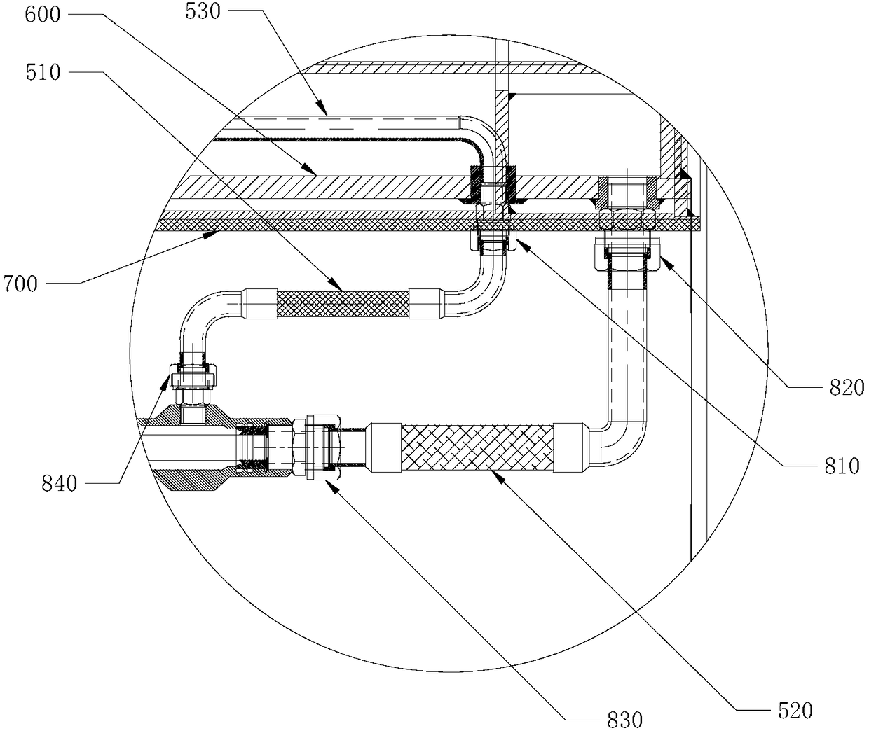
[0064] On the basis of Embodiment 1 or Embodiment 2, a connection method of the first channel 410 and the medium inlet, and the second channel 420 and the medium outlet is as follows: the first channel 410 is connected to the medium inlet through the medium inlet pipe 510, and / Alternatively, the second channel 420 is connected to the medium outlet through the medium return pipe 520.

[0065] When the first channel 410 is connected to the medium inlet through the medium inlet pipe 510, and the second channel 420 is connected to the medium outlet through the medium return pipe 520;

[0066] Both the medium inlet pipe 510 and the medium return pipe 520 are hoses, which are easy to install and disassemble, which is convenient for later replacement. At the same time, the hose itself can be bent to save space;

[0067] The medium return pipe 520 and the second channel 420, the medium return pipe 520 and the medium outlet, the medium inlet pipe 510 and the medium inlet respectively pass th...


PUM


Abstract

The invention discloses a drafting roller for special polyethylene fibers, a drafting machine and a drafting device. The drafting roller comprises a rotating shaft, a roller body, a jacket roller anda heat-conduction medium tube; the rotating shaft is internally provided with a first channel and a second channel; the roller body is fixedly connected with the rotating shaft; the jacket roller is provided with a medium inlet, a medium outlet and a hollow medium flow cavity, the medium flow cavity is communicated with the first channel through the medium inlet, and the medium flow cavity is communicated with the second channel through the medium outlet. The drafting roller has the advantages that the thermal efficiency is high, no disturbance is caused to the fibers, the drafting roller canuniformly dry, evenly heat and highly draft the nascent fibers in a stable and tensioned state without leakage, and an extraction agent is efficiently recycled. A drying box, a seven-roller drafting machine and a drafting hot box in the prior art are replaced, the overall centralized intelligent control over after-spinning of the high-strength and high-modulus polyethylene fibers is achieved, theproduct quality is improved, the energy consumption is reduced, the production rate and the premium grade rate are increased, and the number of workers and the labor intensity are reduced.

Description

Technical field [0001] The invention relates to the technical field of chemical equipment, in particular to a drafting roller, a drafting machine and a drafting device for special polyethylene fibers. Background technique [0002] High-strength and high-modulus polyethylene fiber Polyethylene fiber is the third-generation special fiber in the world today. Its strength is as high as 30.8cN / dtex, and its specific strength is the highest among chemical fibers. It also has good wear resistance, impact resistance, corrosion resistance and light resistance. . It can be directly made into ropes, cables, fishing nets and various fabrics: bulletproof vests and clothes, cut-resistant gloves, etc. The bulletproof effect of bulletproof vests is better than that of aramid. Internationally, high-strength and high-modulus polyethylene fibers have been woven into ropes of different deniers, replacing traditional steel cables and synthetic fiber ropes. High-strength and high-modulus polyethylen...

Claims


Application Information

Patent Timeline
Patent Type & Authority Applications(China)
IPC IPC(8): D01D5/16D01D10/02D01D10/06D01D11/00
CPCD01D5/16D01D10/02D01D10/06D01D11/00
Inventor 史小军
Owner 河北和泰航天科技有限公司
Why Eureka
Try Eureka