Solid particle heat absorber for solar thermal power generation

A technology of solar thermal power generation and solid particles, which is applied to solar thermal power generation, solar collectors, solar heat storage, etc., can solve the problems of small temperature rise, blockage of solid particle flow, and no enhancement of heat transfer in pores, and achieves structural Simple, effect with reduced likelihood of particle clogging

Active Publication Date: 2018-08-28
INST OF ELECTRICAL ENG CHINESE ACAD OF SCI
View PDF8 Cites 21 Cited by
  • Summary
  • Abstract
  • Description
  • Claims
  • Application Information

AI Technical Summary

Problems solved by technology

[0004] U.S. Patent US9732986B2 discloses a method of using porous media to slow down the falling speed of solid particles and enhance heat transfer. However, due to the small pores of porous media materials, flowing solid particles are easily congested in it, destroying its flow process.
European patent EP 2630219A2 discloses a heat absorber that uses solid particles to fluidize and absorb heat in an opaque metal tube, which can effectively control the flow of particles and enhance heat absorption, but this patent uses the indirect heat absorption and heat exchange of metal tubes, The principle is the same as that of the traditional molten salt heat sink, and there are also problems of thermal stress damage and local hot spots being melted after the metal tube is heated unevenly. Abrasion, which affects the service life of metal pipes
Chinese patent CN102679578A discloses a free-falling solid particle heat absorber in a quartz glass tube bundle. The heated particles transfer heat t

Method used


Image

  • Solid particle heat absorber for solar thermal power generation
  • Solid particle heat absorber for solar thermal power generation
  • Solid particle heat absorber for solar thermal power generation

Examples


Embodiment Construction

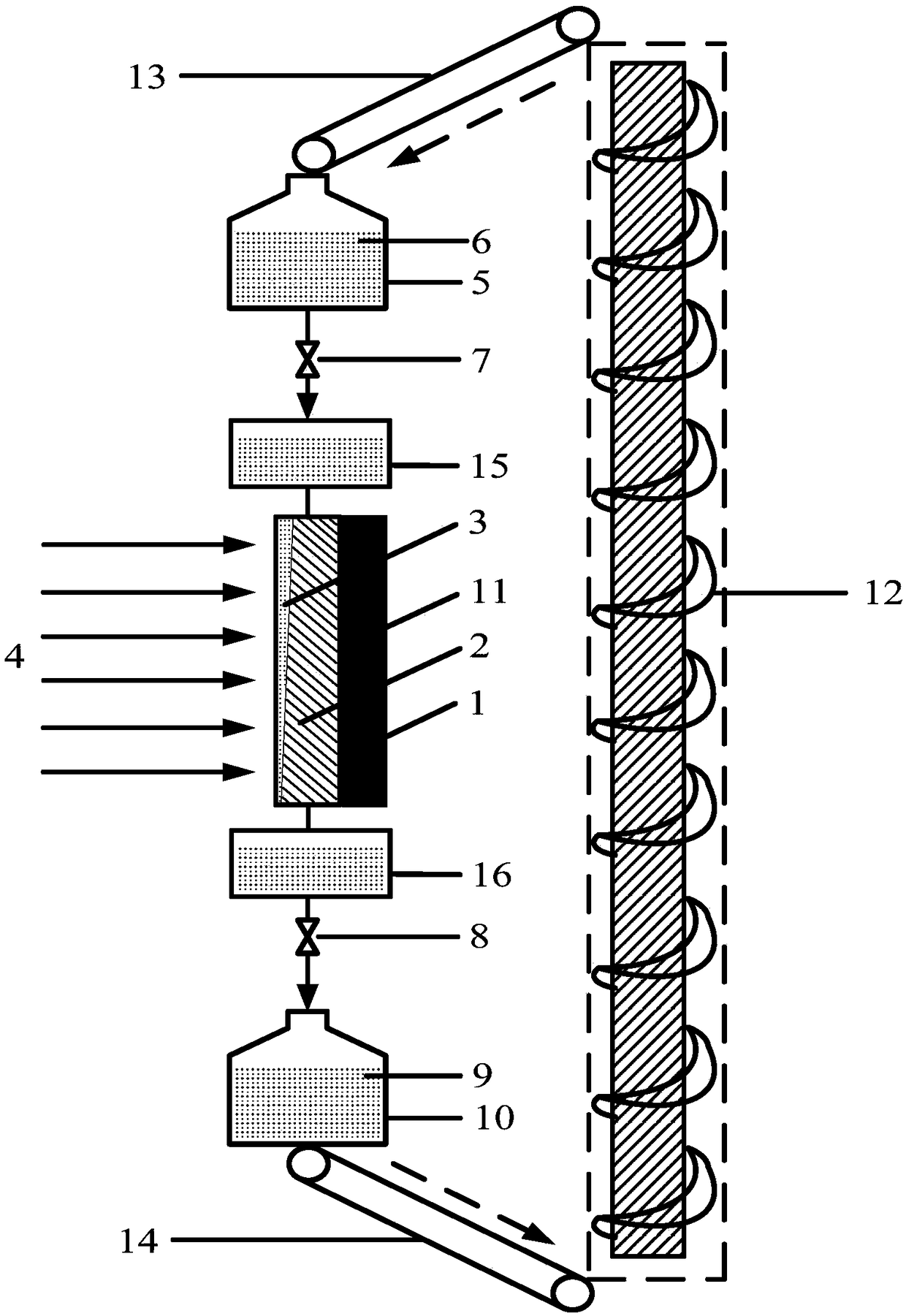
[0046] The present invention will be further described below in conjunction with the accompanying drawings and specific embodiments.

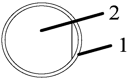
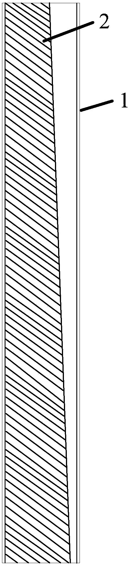
[0047] Such as figure 1 As shown, the solid particle heat absorber of the present invention includes a quartz glass tube bundle 1, an inner insulation layer 2, solid particles 3, a low-temperature particle storage tank 5, a low-temperature particle storage tank outlet valve 7, a high-temperature particle storage tank inlet valve 8, a high-temperature particle storage tank Tank 10 , outer insulation 11 , screw elevator 12 , conveyors 13 , 14 , particle distributor 15 and particle collector 16 . ; The quartz glass tube bundle 1 is arranged facing the radiation energy flow 4 . The inner insulation layer 2 is located on the backlight side of the quartz glass tube of the quartz glass tube bundle 1; the solid particles 3 are installed in the quartz glass tube bundle 1; the outer insulation layer 11 surrounds the outer circumference of the quartz gla...


PUM


Abstract

The invention relates to a solid particle heat absorber for solar thermal power generation. A quartz glass tube bundle (1) filled with solid particles (3) is arranged facing a radiant flux (4). An inner heat-insulation layer (2) is located on the backlight side in a tube of the quartz glass tube bundle (1); and the change of a sectional area of a solid particle runner is realized through adjustinga geometrical shape of the inner heat-insulation layer (2). An outer heat-insulation layer (11) surrounds the periphery of the quartz glass tube bundle (1) and is located on one surface back to the radiant flux. A first solid particle valve (17) is arranged on the bottom part of a particle distributor (15) on the upper part of the quartz glass tube bundle (1). A second solid particle valve (18) is arranged on the top part of a particle collector (16) on the lower part of the quartz glass tube bundle (1). A low-temperature particle storage tank (5) is arranged above the particle distributor (15), and a high-temperature particle storage tank (10) is arranged under the particle collector (16). A valve is arranged between the low-temperature particle storage tank (5) and the particle distributor (15); and a valve is arranged between the particle collector (16) and the high-temperature particle storage tank (10).

Description

technical field [0001] The invention relates to a heat absorber for solar thermal power generation, in particular to a solid particle heat absorber. Background technique [0002] The heat absorber of the tower solar thermal power generation system is placed on the top of the heat absorbing tower, and the heliostats on the ground automatically track the sun and accurately project the concentrated reflected light into the heat absorber. The heat transfer fluid in the heat absorber can be water, molten salt, liquid metal, air, supercritical carbon dioxide, solid particles, etc., and the heat energy generated after the heat transfer fluid in the heat absorber is heated is further converted into a steam turbine or a gas turbine. The heat energy of the power generation working medium in the forestry machine, the power generation working medium drives the generator set to generate electric energy. Before 2007, the United States contributed almost 740MW of installed capacity of sol...

Claims


Application Information

Patent Timeline
IPC IPC(8): F24S60/00
CPCY02E10/40
Inventor 聂辅亮白凤武王志峰
Owner INST OF ELECTRICAL ENG CHINESE ACAD OF SCI
Why Eureka
Try Eureka