

Set system for removing PM 2.5 by wet method and recovering waste heat
A waste heat recovery and complete system technology, which is applied in the field of energy conservation and environmental protection, can solve the problems of general dust removal effect of industrial waste gas, achieve good economy, prevent secondary dust, and reduce volume
- Summary
- Abstract
- Description
- Claims
- Application Information
AI Technical Summary
Problems solved by technology
Method used
Image

Examples
Embodiment Construction
[0021] The present invention is described in further detail now in conjunction with accompanying drawing. These drawings are all simplified schematic diagrams, which only illustrate the basic structure of the present invention in a schematic manner, so they only show the configurations related to the present invention.
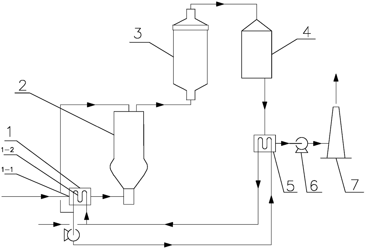
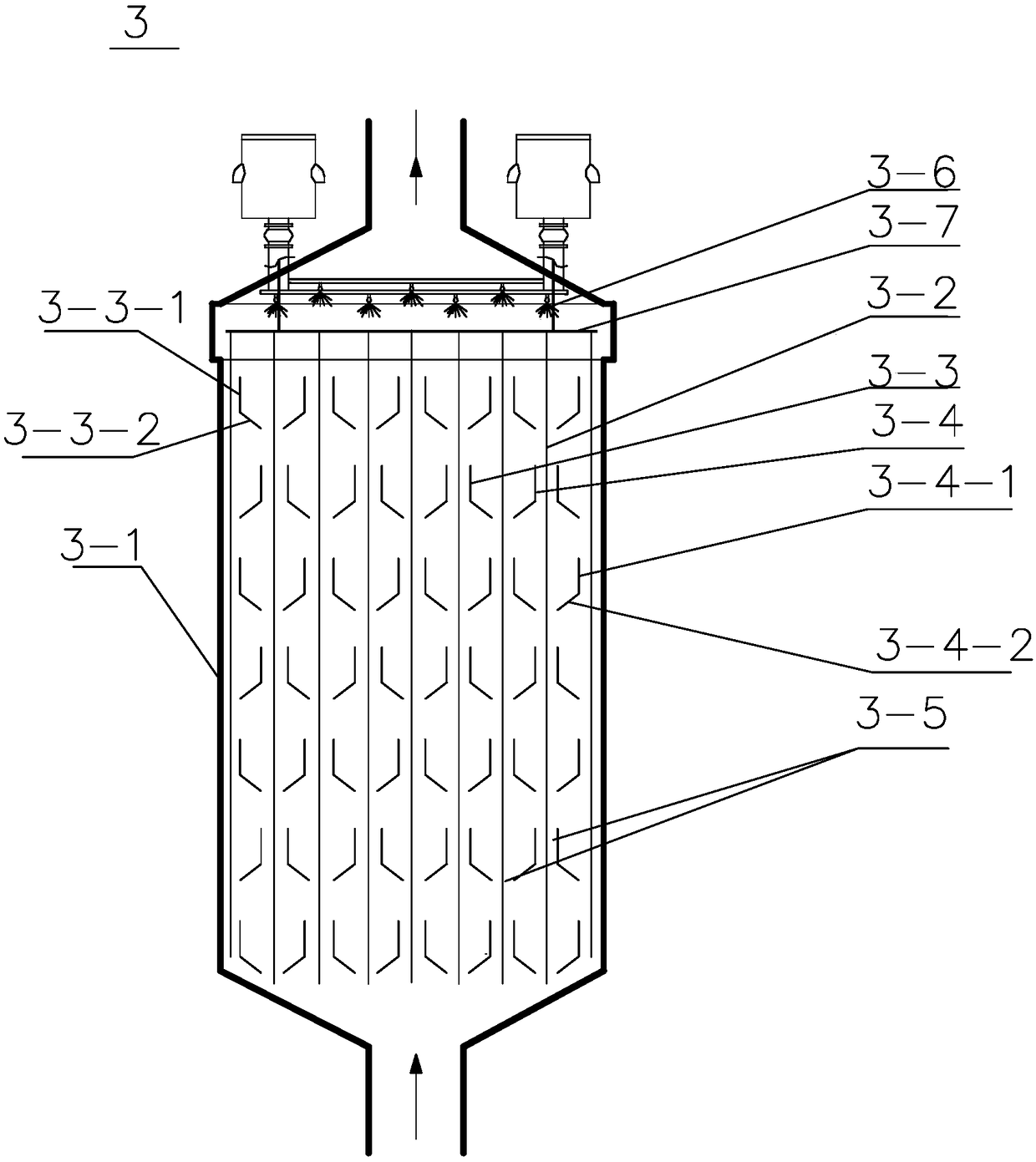
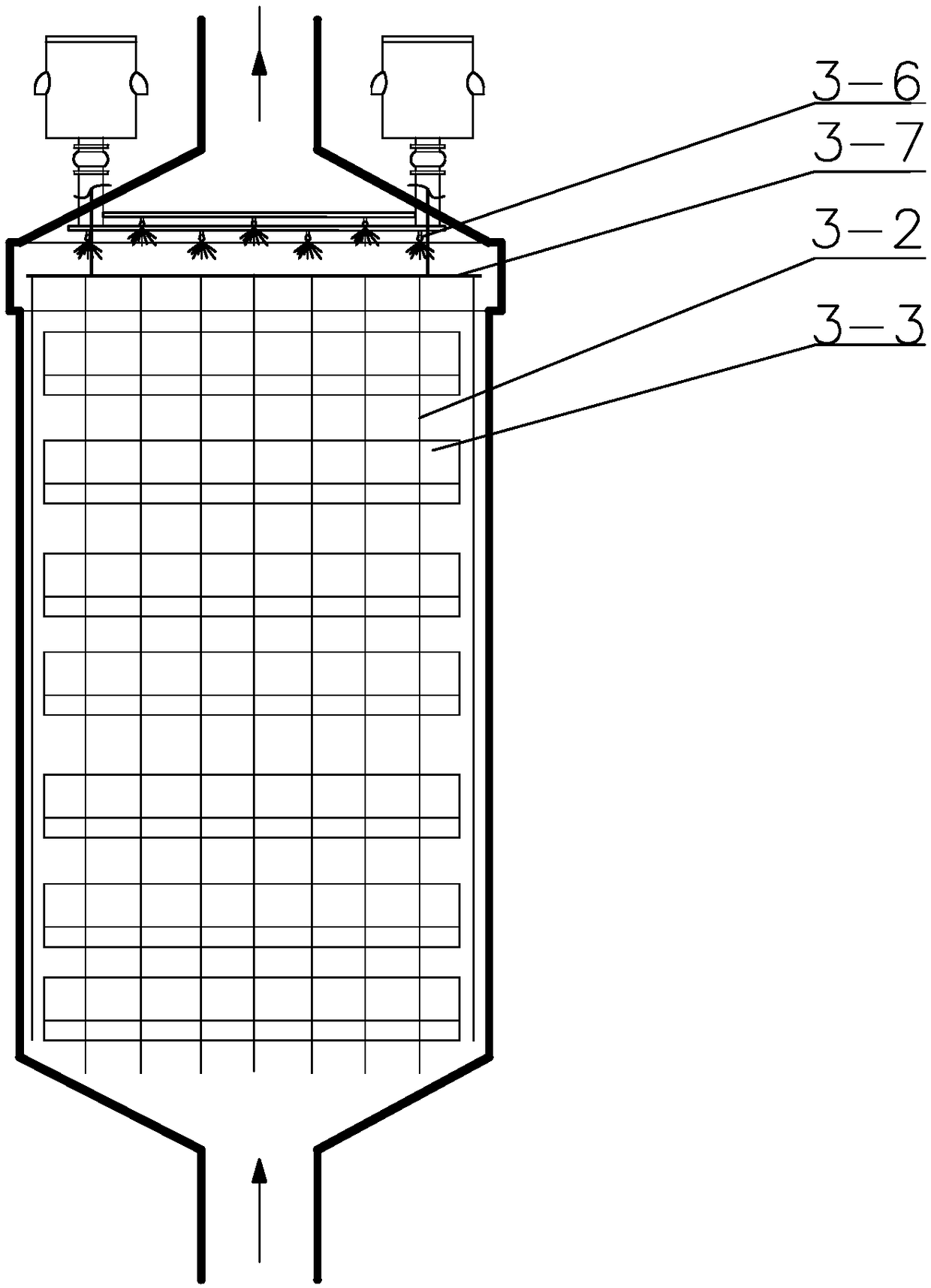
[0022] Such as Figure 1-6 As shown, it is the best embodiment of the present invention, a complete system for wet removal of PM2.5 and waste heat recovery and utilization, including exhaust gas cooler 1, water vapor phase change condensing chamber arranged in series from front to back according to the process sequence 2. Electrostatic precipitator 3, desulfurization tower 4, exhaust gas reheater 5, induced draft fan 6 and chimney 7, exhaust gas cooler 1 is provided with exhaust gas inlet 1-1, and exhaust gas cooler 1 is provided with heat exchanger 1-2 , the electrostatic precipitator 3 is a vertical conical electrostatic precipitator, the vertical conical e...
PUM
 Abstract
Description
Claims
Application Information