
Method used for improving residual compressive stress of laser additive manufacturing component

A residual compressive stress and laser additive technology, which is applied in the field of additive manufacturing components, can solve the problems that the tensile stress cannot be completely eliminated, and the tensile stress of components cannot be completely eliminated, so as to prevent outward diffusion, prevent burns, and improve fatigue performance Effect

Inactive Publication Date: 2018-09-04
AVIC BEIJING INST OF AERONAUTICAL MATERIALS
View PDF7 Cites 6 Cited by
  • Summary
  • Abstract
  • Description
  • Claims
  • Application Information

AI Technical Summary

Problems solved by technology

For this method, under certain conditions, it can reduce the residual stress of drawing by 70% in the component, but it cannot completely eliminate the stress of drawing in the component.
[0007] The above three methods can control the tensile stress inside and on the surface of the additively manufactured component, but they cannot completely eliminate the tensile stress inside the component, and cannot generate compressive stress on the surface and inside of the material.

Method used


Image

  • Method used for improving residual compressive stress of laser additive manufacturing component
  • Method used for improving residual compressive stress of laser additive manufacturing component

Examples


Embodiment Construction

[0031] The present invention will be further described below in conjunction with accompanying drawing.

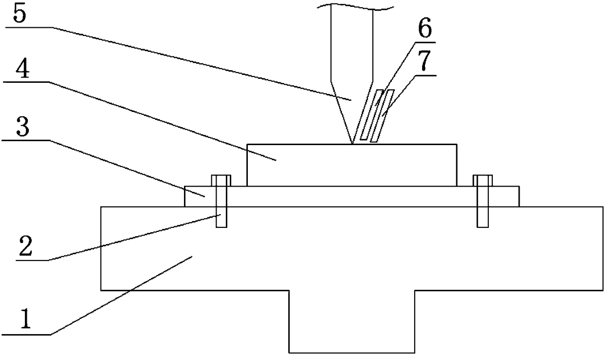
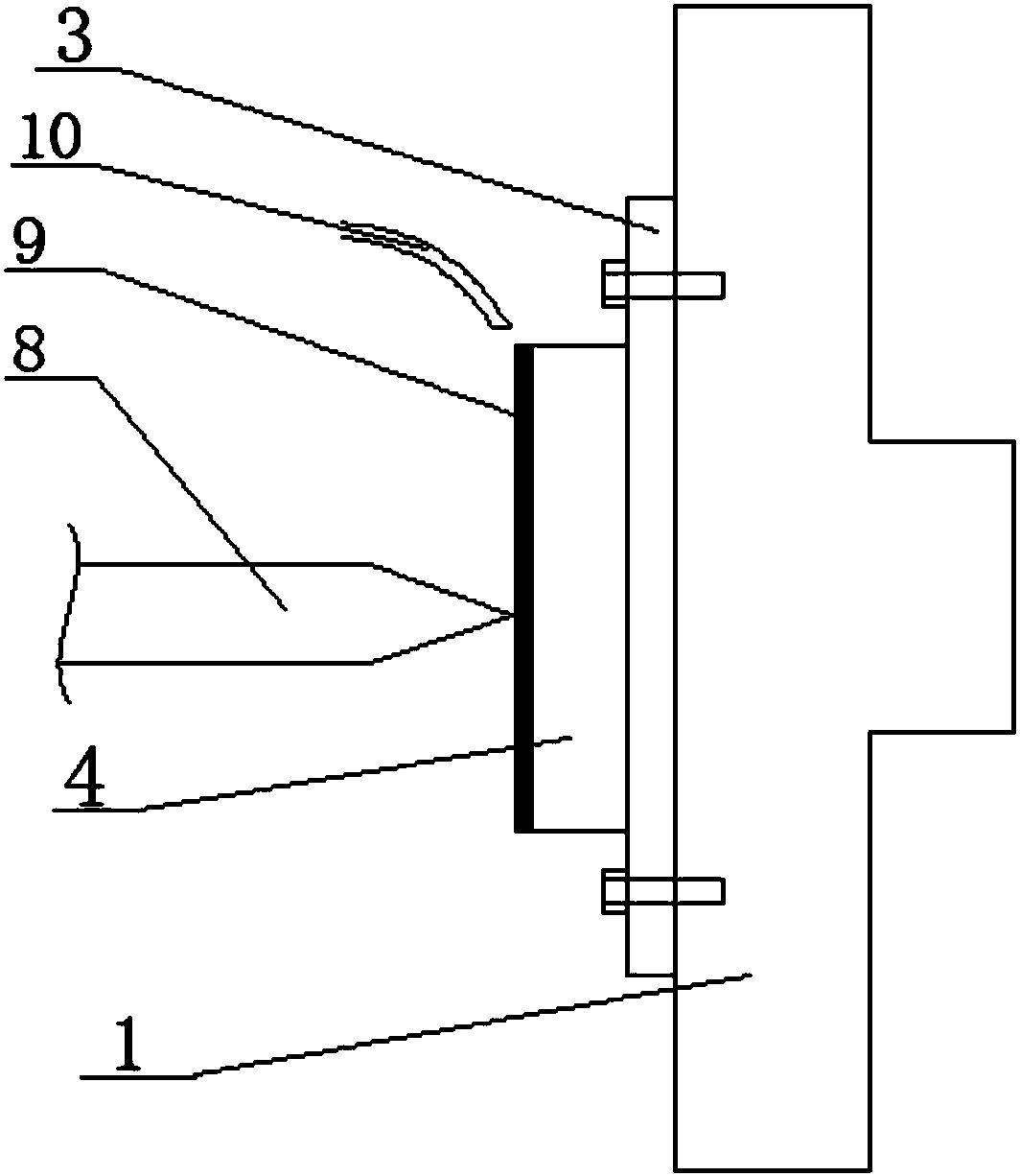
[0032] Such as figure 1 As shown, the equipment used for additive manufacturing includes a mechanical arm 1, a clamp 2, a substrate 3, a powder feeding device 6, an air inlet device 7, an opaque protective film 9, an infusion tube 10, a first laser (not shown in the figure) out) and a second laser (not shown).

[0033] The clamp 2 is arranged on the robot arm 1 for fixing the substrate 3 on the robot arm 1 . The clamp 2 may be a bolt connecting the base plate 3 and the robot arm 1 to each other. The robot arm 1 can switch between the state of horizontal arrangement and vertical arrangement of substrate 3 . The powder feeding device 6 is used for laying powder material on the substrate 3 . The air intake device 7 is used for inputting protective gas while the powder feeding device 6 lays the powder material. The shielding gas is preferably an inert gas, more preferably ...


PUM

PropertyMeasurementUnit
Thicknessaaaaaaaaaa
Wavelengthaaaaaaaaaa
Pulse widthaaaaaaaaaa

Abstract

The invention relates to a method of additive manufacturing components, in particular to a method used for improving residual compressive stress of a laser additive manufacturing component. The methodcomprises the steps that powder materials are sequentially subject to agglomeration on the face of a substrate to form multiple lamination pieces which are stacked layer by layer from bottom to top,and in the process, after every time one or multiple lamination pieces are formed, the steps from S10 to S30 are executed; S10, a light-proof protection film is pasted on the surfaces of the lamination pieces, and the surface of the protection film is coated with liquid to form a liquid thin film on the protection film; S20, a pulse laser beam is adopted to shoot the protection film to enable theinterior of the additive manufacturing component to generate the compressive stress; S30, the protection film is removed. Pressure peaks formed by impact waves generated by the technology exceed the yield strength of the lamination layer of the lamination pieces to enable the interior of the lamination layer of the lamination pieces to generate plastic deforming and the residual compressive stress, all stretching stress can be offset, the fatigue crack extension can be effectively reduced, and the fatigue performance of the laser additive manufacturing component can be improved.

Description

technical field [0001] The invention relates to a method for additively manufacturing a component, in particular to a method for increasing the residual compressive stress of a laser additively manufactured component. Background technique [0002] Additive Manufacturing (AM), commonly known as 3D printing, is a fusion of computer-aided design, material processing and forming technology, based on digital model files, through software and numerical control system to combine special metal materials, non-metal materials and medical biological Materials are piled up layer by layer according to extrusion, sintering, melting, photocuring, spraying, etc., to create a manufacturing technology for physical objects. Compared with the traditional processing mode of raw material removal-cutting and assembly, it is a "bottom-up" manufacturing method through material accumulation, starting from scratch. This makes it possible to manufacture complex structural parts that were restricted by...

Claims


Application Information

Patent Timeline
IPC IPC(8): B22F3/105B33Y10/00
CPCB33Y10/00B22F10/00B22F10/38B22F12/43B22F10/50B22F12/45B22F10/28Y02P10/25
Inventor 黄帅熊华平陈冰清郭绍庆刘伟李能秦仁耀
Owner AVIC BEIJING INST OF AERONAUTICAL MATERIALS
Learn More