Realizing method and system of vision inertial mileometer

An implementation method and odometer technology, applied in the field of computer vision, which can solve the problems of high power consumption, poor real-time performance, and difficulty in processing power.

Active Publication Date: 2018-09-04
SHICHEN INFORMATION TECH SHANGHAI CO LTD
View PDF9 Cites 52 Cited by
  • Summary
  • Abstract
  • Description
  • Claims
  • Application Information

AI Technical Summary

Problems solved by technology

[0004] Chinese patent document CN102538781A discloses a mobile robot motion attitude estimation method based on machine vision and inertial navigation fusion, based on the extended Kalman filter framework for attitude tracking, but the accuracy is low
[0008] The techniques disclosed in the above documents are aimed at specific hardware such as binocular cameras and IMUs, but not applicable to monocular cameras and IMUs
Moreover, the system has complex calculations, poor real-time performance, and high power consumption, so it is difficult to be used in mobile devices with weak processing capabilities and low power consumption functions.

Method used


Image

  • Realizing method and system of vision inertial mileometer
  • Realizing method and system of vision inertial mileometer
  • Realizing method and system of vision inertial mileometer

Examples


Embodiment 1

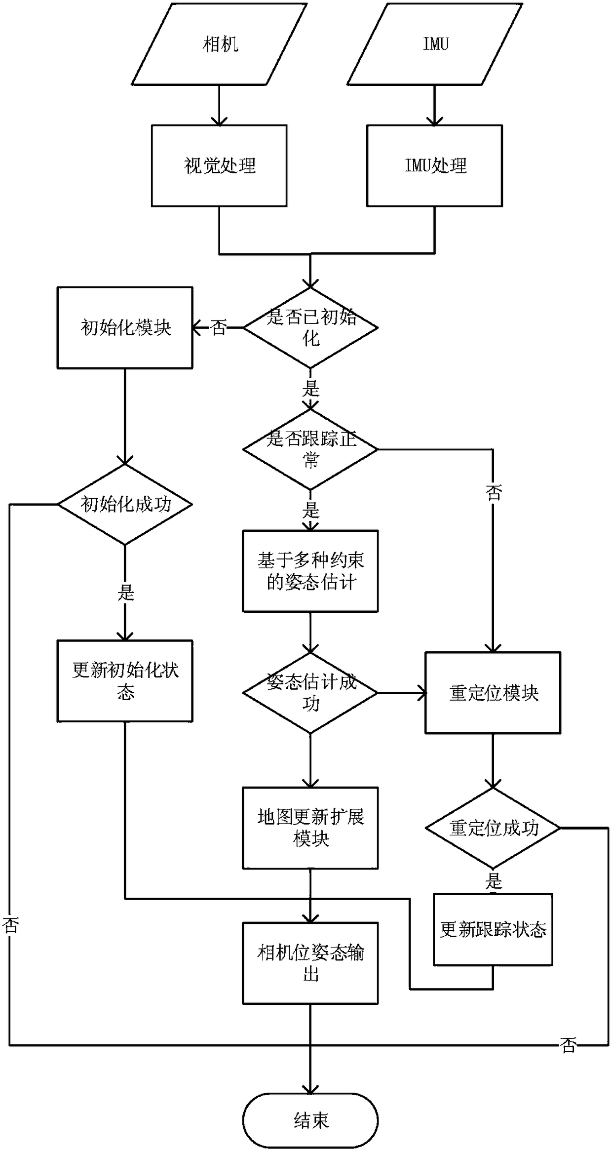
[0068] Such as figure 1 As shown, the implementation method of the visual inertial odometer in the embodiment of the present invention includes the following steps:

[0069] In the first step (S1), the device collects image data in real time through the camera; the angular velocity and acceleration data of the device are collected in real time through an inertial measurement unit (IMU); the IMU includes a gyroscope and an accelerometer, and the angular velocity and acceleration data collected by the IMU are The data can also be referred to as the acquisition data of the IMU for short;

[0070] In the second step (S2), the scene initialization module establishes the initial space of the visual-inertial odometry system based on the image data collected in real time by the camera, the angular velocity data of the device collected by the IMU using the gyroscope, and the acceleration data collected by the accelerometer. 3D map;

[0071] Preferably, the second step (S2) may includ...

Embodiment 2

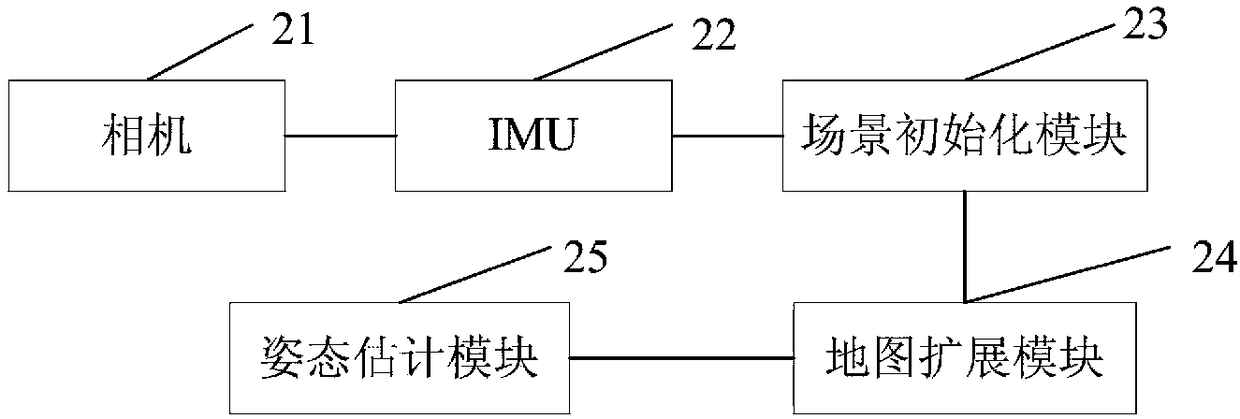
[0088] Such as figure 2 As shown, the embodiment of the present invention also provides a visual-inertial odometry system, including a camera 21, an IMU22, a scene initialization module 23, a map extension module 24 and a pose estimation module 25, wherein:

[0089] Camera 21, for collecting image data in real time;

[0090] IMU22, used to collect angular velocity and acceleration data of the device, the IMU includes a gyroscope and an accelerometer;

[0091] The scene initialization module 23 is used for the establishment of the initial space three-dimensional map of the visual-inertial odometry system;

[0092] The map extension module 24 is used to update the spatial three-dimensional map set up by the scene initialization module 23 in real time;

[0093] The attitude estimation module 25 uses the spatial constraint relationship between the current image feature point and the three-dimensional map point maintained by the map extension module, the feature matching constrain...

Embodiment 3

[0110] The implementation method of the visual inertial odometer provided by the embodiment of the present invention uses a smart phone to perform real-time positioning and tracking of the mobile phone in an unknown indoor environment as an example to specifically illustrate the technical solution of the present invention:

[0111] 301. Use a smart phone equipped with a camera, a gyroscope, and an accelerometer. The smart phone is also integrated with the visual-inertial odometer system provided by the embodiment of the present invention. In the embodiment of the present invention, the smart phone can be regarded as Equipment; the visual-inertial odometer system can obtain the real-time two-dimensional image input of the camera and the input of the IMU in real time; the camera collects images at a fixed frame rate, such as 30 Hz, and the image size collected by the camera can be set according to the actual mobile phone computing power, such as 720p ; The frequency of the gyrosc...


PUM


Abstract

The invention embodiment discloses a realizing method and a system of a vision inertial mileometer. The realizing method comprises following steps: 1, a camera is adopted for real-time acquisition ofimage data, and an IMU is adopted to collect gyroscope and acceleration data; 2, a scene initialization module is adopted to establish an initial space three-dimensional map of a vision inertial mileometer system; 3, a map expansion module is adopted for real-time updating of the initial space three-dimensional map; and 4, an attitude estimation module is used for receiving the position and the attitude of equipment corresponding to each image frame. According to the realizing method, the scene initialization module is adopted to realize system initialization process high in robustness; the attitude estimation module is adopted to realize position and attitude optimization based on vision information and IMU information combined constraints; a repositioning module is adopted for failure treatment and repositioning algorithm, and equipment real-time position and attitude information are obtained. The invention embodiment also discloses a vision inertial mileometer system.

Description

technical field [0001] The embodiment of the present invention relates to a computer vision technology, in particular to a method for realizing a visual inertial odometer. The embodiment of the present invention also relates to a visual-inertial odometer system. Background technique [0002] Real-time tracking of the position and attitude of devices in an unknown environment is one of the core issues in the fields of augmented reality, virtual reality, navigation and control, mobile robots, unmanned driving, and drones. As the most common method to solve such problems, Simultaneous Localization and Mapping (SLAM) has also been widely studied in related fields such as robotics and computer vision. Recently, localization algorithms based on the fusion of computer vision and inertial measurement units have received increasing attention due to their low cost, high accuracy, and strong complementarity. This method of using the device's own camera and IMU (inertial measurement u...

Claims


Application Information

Patent Timeline
Patent Type & Authority Applications(China)
IPC IPC(8): G01C21/16G01C21/20G01C22/00
CPCG01C21/20G01C22/00G01C21/1656
Inventor 王强徐尚张小军
Owner SHICHEN INFORMATION TECH SHANGHAI CO LTD
Why Eureka
Try Eureka