Laser engraving machine, control system and control method

A technology of laser engraving machine and control method, applied in general control system, control/regulation system, computer control and other directions, can solve the problem of failure to consider the redundancy and correlation of feature subsets, less unsupervised methods, and diverse solution sets poor sexual performance

Inactive Publication Date: 2018-09-04
GUANGDONG TECHN COLLEGE OF WATER RESOURCES & ELECTRIC ENG
View PDF7 Cites 4 Cited by
  • Summary
  • Abstract
  • Description
  • Claims
  • Application Information

AI Technical Summary

Problems solved by technology

In addition, the multi-objective feature selection algorithm finally obtains a series of compromise solutions, from which it is necessary to select a solution with excellent performance, but currently there are few unsupervised methods available
The main difficulty lies in: (1) The designed feature subset evaluation function and search strategy fail to consider the redundancy and correlation of the feature subset; (2) The evaluation criteria also do not consider the selection of the feature subset dimension. The impact of classification effectiveness; (3) The unsupervised way to extract the feature dimension and the importance ranking of feature subsets in the Pareto solution set of the multi-objective optimization algorithm has not yet been resolved
[0010] In multi-objective optimization algorithms, low convergence efficiency, poor diversity of solution sets and premature falling into local optimum problems are common in multi-objective optimization algorithms.

Method used


Image

  • Laser engraving machine, control system and control method
  • Laser engraving machine, control system and control method
  • Laser engraving machine, control system and control method

Examples


Embodiment Construction

[0110] In order to further understand the content, features, and effects of the present invention, the following embodiments are exemplified, and are described in detail below with accompanying drawings.

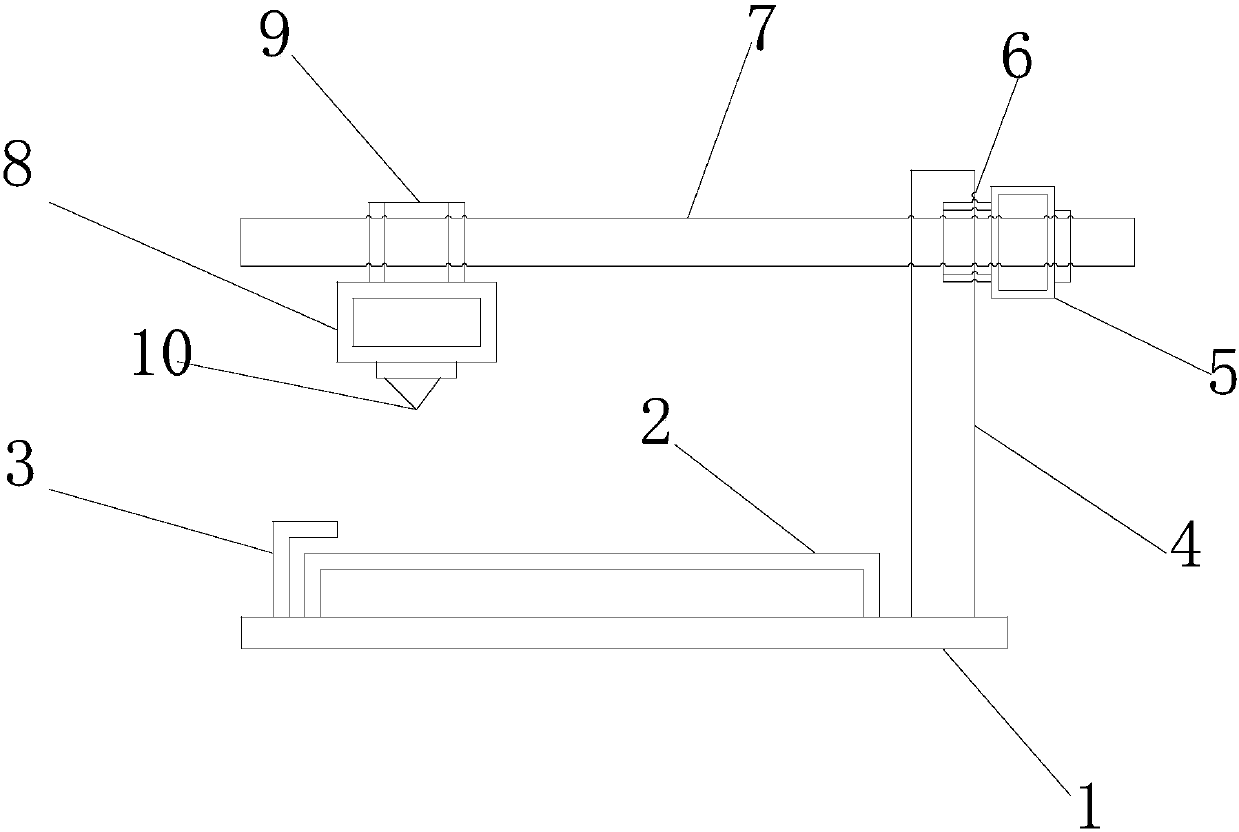
[0111] Such as Figure 1-Figure 2 As shown, the laser engraving machine provided by the embodiment of the present invention is provided with a base 1, a stage 2, a fixing frame 3, a vertical guide 4, a vertical stepping motor 5, a vertical gear 6, a horizontal guide 7, and a horizontal step. Into the motor 8, the horizontal gear 9, the laser cutter head 10.

[0112] The stage 2 is located above the base 1 and fixed on the base 1 by bolts. The fixing frame 3 is located on the left side of the base 1 and fixed on the base 1 by bolts. The vertical rail 4 is located on the right side of the base 1 and fixed on the base by bolts. On 1, the horizontal guide rail 7 is located on the vertical guide rail 3, the vertical stepping motor 5 is located on the horizontal guide rail 7, and is fi...


PUM


Abstract

The invention belongs to the laser engraving processing technology field and discloses a laser engraving machine, a control system and a control method. The method is characterized by extracting the image data information of a product to be engraved from the pre-stored database of the products to be engraved; processing the image data information of the product to be engraved, and using the cubicB-spline curve construction model to construct the three-dimensional graph of the model of the product to be engraved; scanning the coordinate information of the three-dimensional graph and acquiringthe real coordinate value of the three-dimensional graph; according to the real coordinate value, using the decimal coding mode of a particle swarm algorithm coding mode to control the operation pathof a vertical stepping motor by a vertical stepping motor control module; driving a vertical gear to reach the setting position of the product to be engraved; and according to the real coordinate value, regulating and controlling a laser cutter head to reach the setting position of the product to be engraved by a horizontal stepping motor control module. In the invention, the design is reasonable,engraving of substances with different heights and thicknesses and different shapes and sizes can be satisfied, the engraving is accurate and work efficiency is greatly increased.

Description

Technical field [0001] The invention belongs to the technical field of laser engraving and processing, and in particular relates to a laser engraving machine, a control system and a control method. Background technique [0002] At present, the existing technology commonly used in the industry is as follows: [0003] At present, laser engraving is based on numerical control technology and laser is the processing medium. The physical degeneration of the processing material that is instantaneously melted and vaporized under the laser engraving irradiation can make the laser engraving achieve the purpose of processing. Laser engraving is the use of laser technology to engrave characters on objects. The characters engraved by this technology have no nicks, the surface of the object is still smooth, and the writing will not wear out. Most of the existing laser engraving can only engrave thinner materials, and cannot engrave materials of different heights and thicknesses, which has cert...

Claims


Application Information

Patent Timeline
IPC IPC(8): G05B19/408B23K26/362
CPCG05B19/4086B23K26/361G05B2219/35356
Inventor 李殊骁邵忠良黄诚刘江帆王思婷
Owner GUANGDONG TECHN COLLEGE OF WATER RESOURCES & ELECTRIC ENG
Why Eureka
Try Eureka