
Boiler burning pulverized coal heating equipment

A technology for heating equipment and pulverized coal, used in lighting and heating equipment, combustion equipment, block/powder fuel preparation, etc. Effect

Pending Publication Date: 2018-09-07
北京蓝爱迪电力技术有限公司
View PDF0 Cites 0 Cited by
  • Summary
  • Abstract
  • Description
  • Claims
  • Application Information

AI Technical Summary

Problems solved by technology

[0005] The purpose of the present invention is to overcome the deficiencies in the prior art and provide a boiler with pulverized coal heating equipment, which can effectively use the system steam turbine extraction to increase the temperature of the pulverized coal before entering the furnace, improve heat exchange efficiency, and prolong the durability of the heating equipment. Longer grinding life and lower flow resistance, thus solving the problem of easy accumulation and deflagration of the high-speed flowing air-powder mixture passing through the heat exchanger

Method used


Image

  • Boiler burning pulverized coal heating equipment
  • Boiler burning pulverized coal heating equipment
  • Boiler burning pulverized coal heating equipment

Examples


Embodiment 1

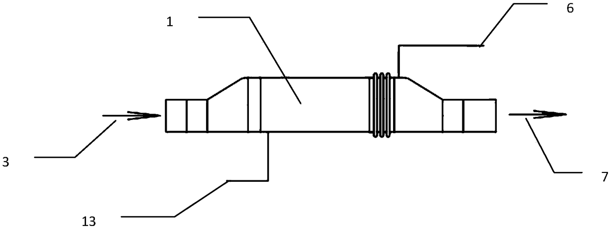
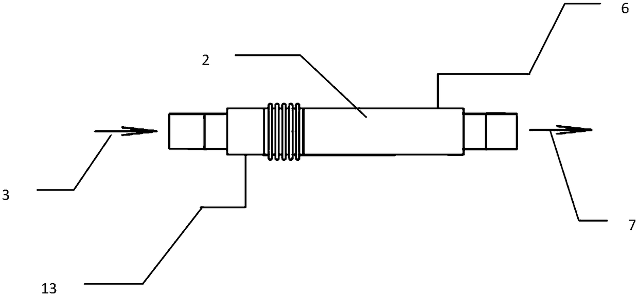
[0047] Such as figure 1 , Figure 4-1 to Figure 5-2 As shown, the boiler of the present invention uses pulverized coal heating equipment, which includes A-type pulverized coal heating equipment 1 and B-type pulverized coal heating equipment 2; A-type pulverized coal heating equipment 1 and B-type pulverized coal heating equipment 2 are arranged in series on the raw coal The other end of the A-type pulverized coal heating equipment 1 is connected to the coal mill 3; the other end of the B-type pulverized coal heating equipment 2 is connected to the boiler furnace burner 7; and A transitional steam pipeline 4 and a transitional pulverized coal pipeline 5 are provided between the A-type pulverized coal heating equipment 1 and the B-type pulverized coal heating equipment 2; a drain outlet 13 is provided on the A-type pulverized coal heating equipment 1; The heating equipment 2 is provided with a steam turbine extraction pipeline 6; wherein:

[0048] The A-type pulverized coal he...

Embodiment 2

[0063] Such as figure 2 , Pic 4-1 , Figure 4-2 Shown, the boiler of the present invention burns pulverized coal heating equipment, and it comprises: A type pulverized coal heating equipment 1 is arranged on the raw pulverized coal pipeline, is connected as one with the raw pulverized coal pipeline; The coal machine 3 is connected, and its other end is connected with the boiler furnace burner 7; and a drain outlet 13 is provided on the A-type pulverized coal heating equipment 1; a steam turbine extraction pipeline 6 is also provided on the A-type pulverized coal heating equipment 1.

[0064] Wherein, the structure of the A-type pulverized coal heating equipment 1 is the same as that of the A-type pulverized coal heating equipment 1 in Embodiment 1, so it will not be repeated here.

Embodiment 3

[0066] Such as image 3 , Figure 5-1 , Figure 5-2 Shown, the boiler of the present invention burns pulverized coal heating equipment, and it comprises: B type pulverized coal heating equipment 2 is arranged on the raw pulverized coal pipeline, is connected as one with the raw pulverized coal pipeline; The coal machine 3 is connected, and its other end is connected with the boiler furnace burner 7; and the B-type pulverized coal heating equipment 2 is provided with a drainage outlet 13;

[0067] Wherein, the structure of the B-type pulverized coal heating equipment 2 is the same as that of the B-type pulverized coal heating equipment 2 in Embodiment 1, so it will not be repeated here.


PUM


Abstract

The invention relates to boiler burning pulverized coal heating equipment. The boiler burning pulverized coal heating equipment comprises A-type pulverized coal heating equipment and B-type pulverizedcoal heating equipment. The A-type pulverized coal heating equipment and the B-type pulverized coal heating equipment are connected and arranged on a raw pulverized coal pipeline. The other end of the A-type pulverized coal heating equipment is connected with a coal mill, and the other end of the B-type pulverized coal heating equipment is connected with a boiler furnace burner. A transition steam pipeline and a transition pulverized coal pipeline are arranged between the A-type pulverized coal heating equipment and the B-type pulverized coal heating equipment. A dewatering outlet is formed in the A-type pulverized coal heating equipment. A steam turbine steam exhaust pipeline is arranged on the B-type pulverized coal heating equipment. The boiler burning pulverized coal heating equipmentis suitable for heat exchange of a coal mill air and powder mixture, steam turbine exhausted steam and any two gas-solid two-phase media flowing at high speed, different steam parameters can be selected according to actual coal types, and the A-type pulverized coal heating equipment and the B-type pulverized coal heating equipment are matched and combined to be used. The problems that heating equipment is short in wearing life, low in heat exchange efficiency and large in flow resistance, and suffers from accumulative detonation are solved.

Description

technical field [0001] The invention relates to a heating device, in particular to a heating device for burning pulverized coal in a boiler. Background technique [0002] At present, the types of coal used in thermal power plants are uneven, and the quality of the coal is poor. Generally, it is a mixed combustion method. However, the moisture and ash content of different coal qualities vary greatly, resulting in the temperature of the pulverized coal before entering the furnace. Coal type requirements. At the same time, due to the temperature limitation of internal bearings and other parts of the coal mill, the outlet temperature of the coal mill is limited to between 65°C and 95°C depending on the type of coal, which makes it impossible to increase the temperature of the pulverized coal before entering the furnace. [0003] For coal with high ash content and high moisture content, fuel ignition delay and low burnout rate lead to increased heat loss from incomplete combusti...

Claims


Application Information

Patent Timeline
IPC IPC(8): F23K1/04
CPCF23K1/04
Inventor 武海王晓余冬曲佳佳付诗萌
Owner 北京蓝爱迪电力技术有限公司
Learn More