Flow battery energy storage system

A technology of flow battery and energy storage system, applied in fuel cells, fuel cell additives, regenerative fuel cells, etc., can solve the loss of positive reactant, the imbalance of positive and negative ion concentrations, and the degree of hydrogen evolution in all-vanadium flow batteries. Small and other problems to achieve the effect of ensuring safe and stable operation and stable capacity

Inactive Publication Date: 2018-09-07
高岩 +2
View PDF8 Cites 9 Cited by
  • Summary
  • Abstract
  • Description
  • Claims
  • Application Information

AI Technical Summary

Problems solved by technology

In this way, when charging and the overpotential is too large, hydrogen will be precipitated at the negative electrode, but the degree of hydrogen evolution in the all-vanadium redox flow battery is small, because the irreversible reaction of hydrogen evolution occurs, resulting in the loss of

Method used


Image

  • Flow battery energy storage system
  • Flow battery energy storage system
  • Flow battery energy storage system

Examples


Embodiment 1

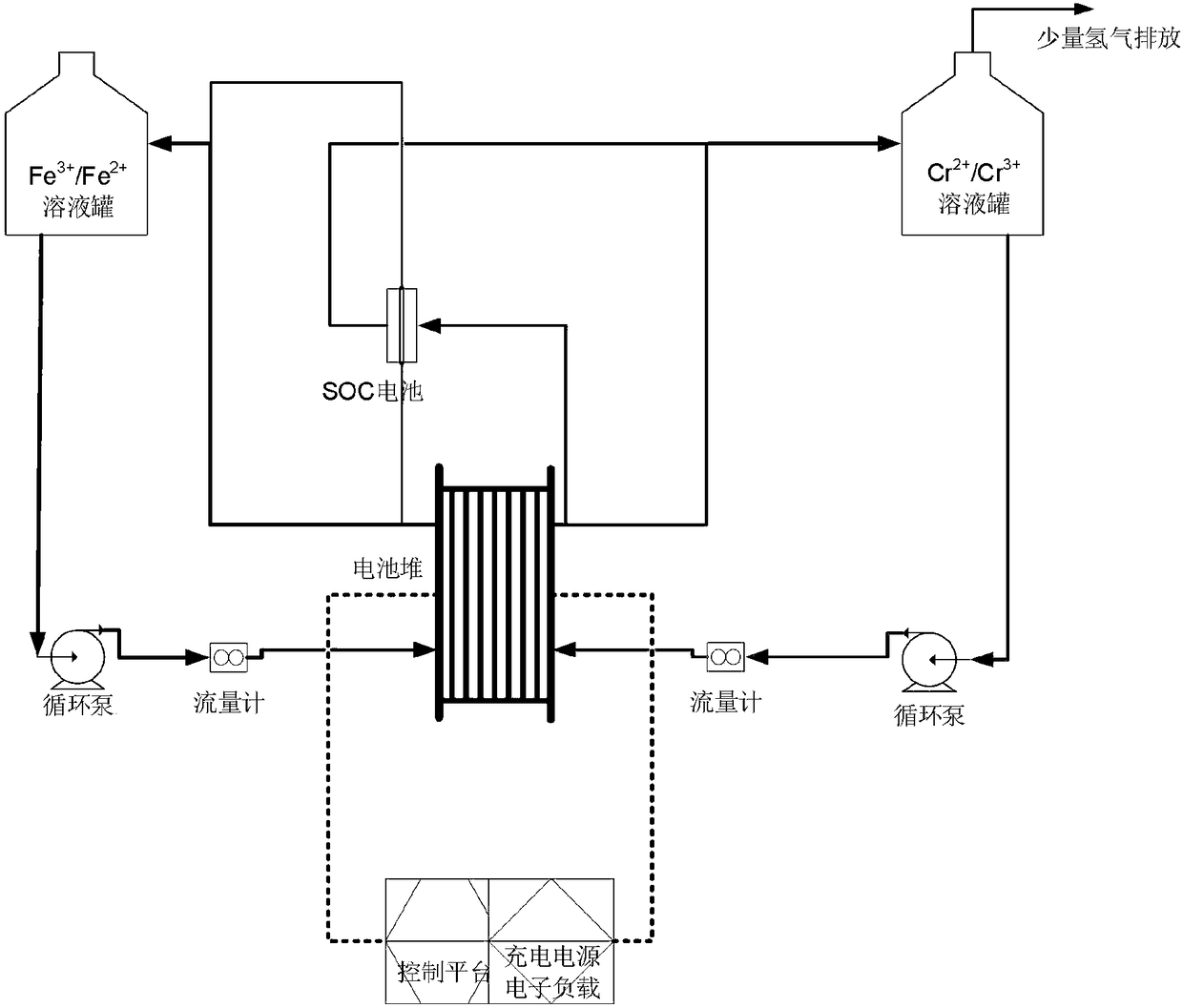
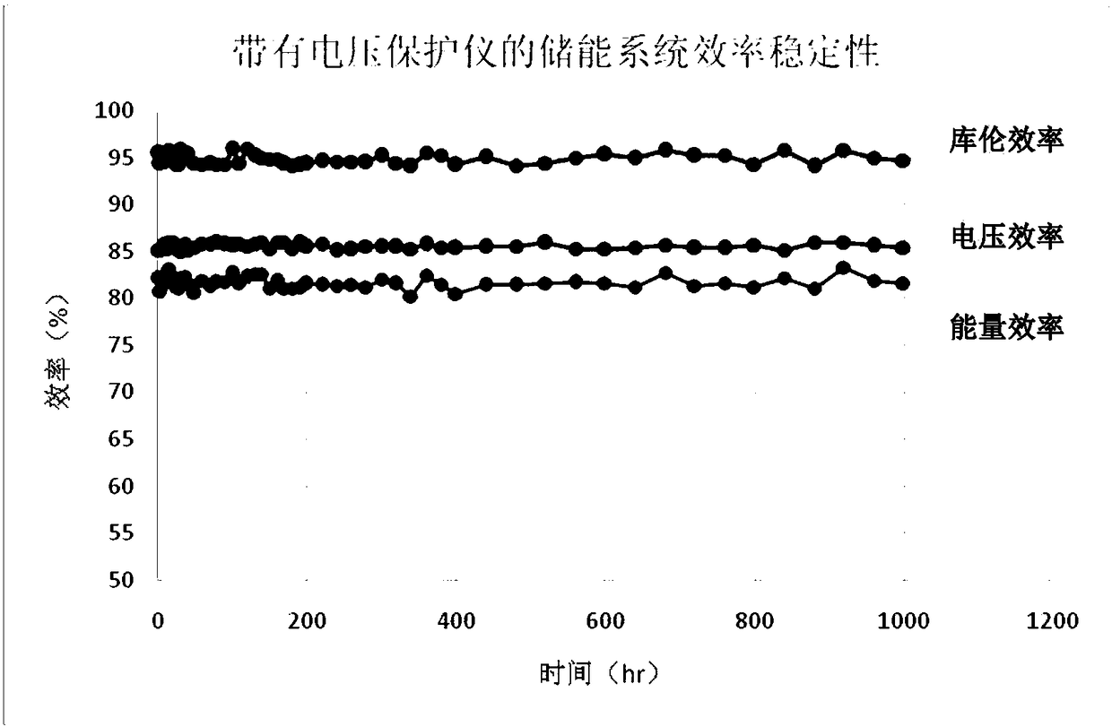
[0041] The all-vanadium redox flow battery energy storage system has a 20kW all-vanadium redox flow battery stack. The all-vanadium redox flow battery stack is composed of two 10kW sub-stacks connected in series on the circuit and fluid pipelines in parallel. Each sub-stack contains 30 For the battery unit, the number of voltage channels of the voltage protection switch should be at least 60, and the voltage with the largest voltage in the charging state, that is, the voltage with the most serious polarization, should be selected by comparison, and the maximum voltage should not be higher than the charging voltage during charging. Set value, usually 1.5V; similarly, when discharging, compare and screen out the voltage with the smallest voltage, that is, the voltage with the most serious polarization, and control the minimum voltage during discharge not to be lower than the safe setting value of discharge voltage, usually 0.85 V. After 1,000 hours of testing and about 500 charg...

Embodiment 2

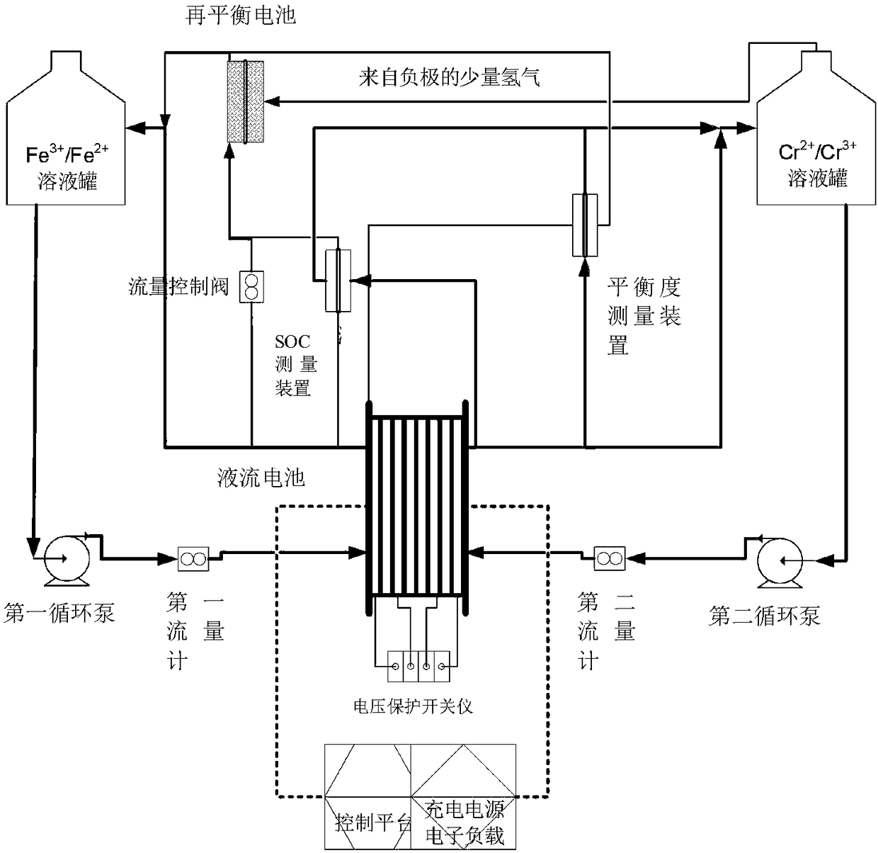
[0043] For a 2kW iron-chromium flow battery energy storage system, a rebalanced battery of about 200W is prepared, and the electrode reaction of the rebalanced battery is as follows

[0044] The positive reaction is

[0045]

[0046] The negative reaction is

[0047]

[0048] Utilizing the above rebalancing battery reaction, when the balance degree of the electrolyte solution of the energy storage system deviates from the preset balance threshold, it is usually set at 3-10%, that is, the rebalancing battery is started to reduce Fe 3+ The operation, the maximum power does not exceed 200W, and the consumed substance is only the hydrogen gas precipitated from the negative electrode, and the hydrogen gas is restored to the system, and there is no need to stop the charging and discharging operation of the main battery. It can completely make up for the Fe caused by the negative hydrogen evolution of the flow battery (the energy loss of a single charge and discharge cycle is ...


PUM


Abstract

The invention discloses a flow battery energy storage system. The flow battery energy storage system comprises a rebalancing battery and a balance degree measuring device, wherein the balance degree measuring device is used for measure the ion balance degree in the flow battery; when the ion balance degree in the flow battery reaches a preset balance threshold, an electrolyte rebalancing battery is started to reduce high valent cations in a positive electrode electrolyte solution, so that the cations in the positive electrode electrolyte solution restores the balance, and the capacity of the whole flow battery energy storage system is stabilized. The capacity of the whole flow battery energy storage system is stable, and the service life of the system is ensured. Moreover, voltage protection is also realized, so that the safety and stability of the system are enhanced.

Description

technical field [0001] The invention relates to the field of new energy, in particular to a liquid flow battery energy storage system. Background technique [0002] The electrochemical redox reaction systems of flow batteries include all-vanadium V / V battery (VRB), sodium polysulfide-bromine (NaS x / Br) batteries, zinc-chlorine (Zn / Cl2) or zinc-bromine (Zn / Br 2 ) batteries and iron-chromium (Fe / Cr) batteries. Among them, the positive and negative electrodes of the VRB and Fe / Cr flow battery systems are in a complete flow state, which has obvious advantages over other solid-state batteries or single flow batteries: long life, stable performance, low cost, and design Flexible and easy to scale up, the construction is not restricted by region, and it is safe and reliable. [0003] As early as the 1970s and 1980s, the Lewis Research Center of NASA (LewisResearch Center) invested a lot of research on the Fe / Cr battery system, overcoming the problem that the electrolyte solutio...

Claims


Application Information

Patent Timeline
IPC IPC(8): H01M8/18H01M8/04186H01M8/04082H01M8/04276H01M8/04313H01M8/0438H01M8/04537H01M8/04955
CPCH01M8/04186H01M8/04201H01M8/04283H01M8/04313H01M8/04388H01M8/04395H01M8/04552H01M8/04619H01M8/04955H01M8/188Y02E60/50
Inventor 高岩曾建华盖丽梅石磊王超
Owner 高岩
Why Eureka
Try Eureka