
Liquid RFID antenna and manufacture method thereof

A manufacturing method and antenna technology, applied in the field of RFID antennas, can solve the problems of poor controllability, unstable working frequency of liquid metal radio frequency antennas, and few applications, and achieve the effect of improving satisfaction, avoiding performance changes, and expanding fit.

Inactive Publication Date: 2018-09-07
苏州德索文信息科技有限公司
View PDF3 Cites 4 Cited by
  • Summary
  • Abstract
  • Description
  • Claims
  • Application Information

AI Technical Summary

Problems solved by technology

At this time, the use of liquid antennas gave technicians a lot of room for imagination. Liquid metal antennas have good tensile properties and have received extensive attention in research and practical applications. However, the biggest problem is that liquid metal RF antennas are stretched. In the process, its operating frequency is unstable and its controllability is poor. It is still difficult to design a liquid antenna that can be stretched and its resonance frequency can be adjusted.
Therefore, although liquid antennas have repairability and complex communication applications that traditional antennas do not have, most of them are still in the laboratory, and there are very few applications.

Method used


Image

  • Liquid RFID antenna and manufacture method thereof
  • Liquid RFID antenna and manufacture method thereof
  • Liquid RFID antenna and manufacture method thereof

Examples


Embodiment Construction

[0031] Embodiments of the present invention are described below through specific examples, and those skilled in the art can easily understand other advantages and effects of the present invention from the content disclosed in this specification. The present invention can also be implemented or applied through other different specific implementation modes, and various modifications or changes can be made to the details in this specification based on different viewpoints and applications without departing from the spirit of the present invention.

[0032] It should be noted that the diagrams provided in this embodiment are only schematically illustrating the basic idea of ​​the present invention, so only the components related to the present invention are shown in the drawings rather than the number, shape and Dimensional drawing, the type, quantity and proportion of each component can be changed arbitrarily during actual implementation, and the component layout type may also be ...


PUM


Abstract

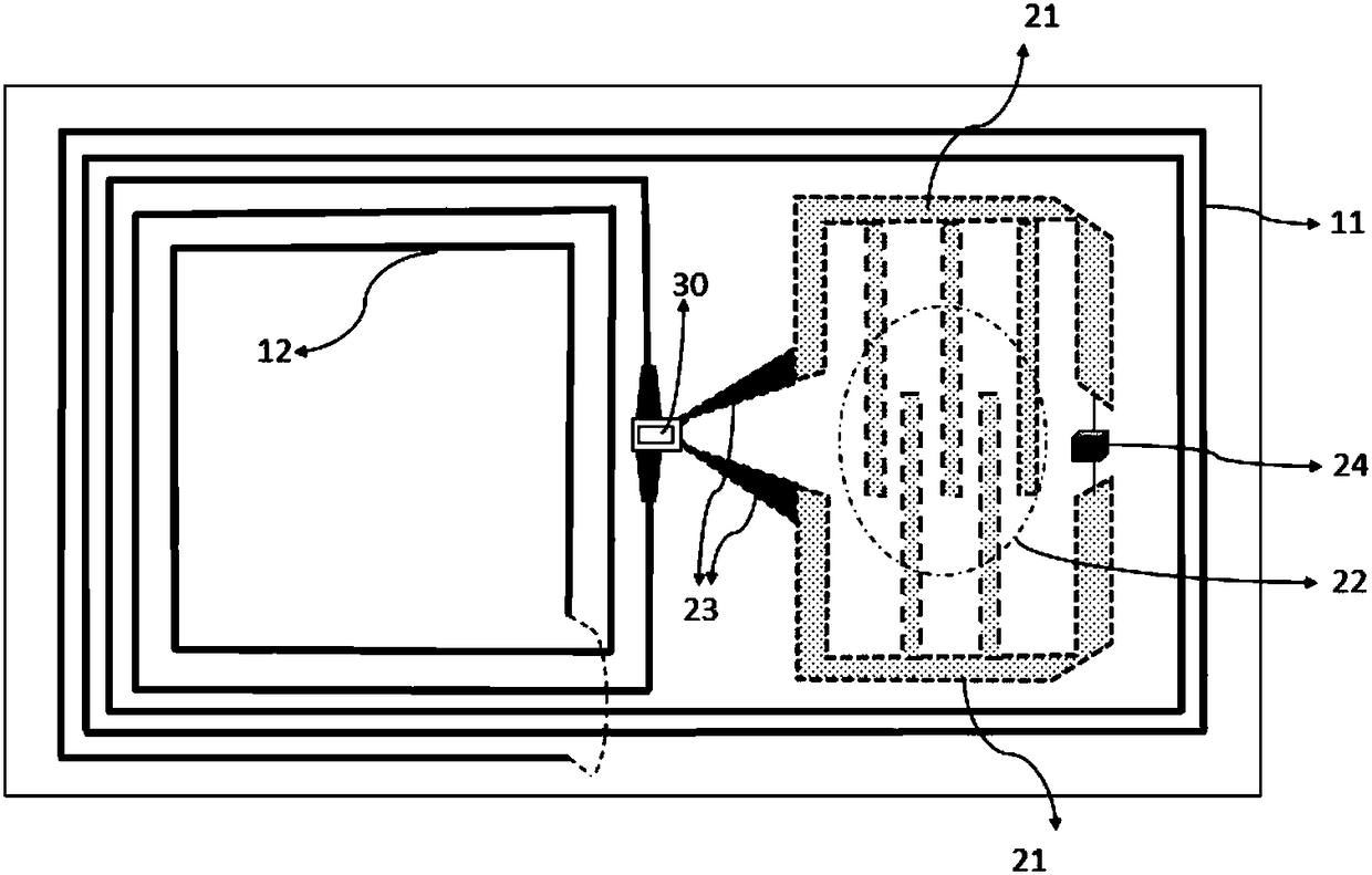
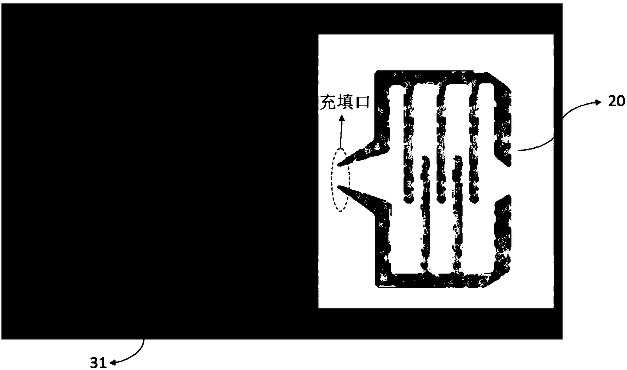
The invention provides a liquid RFID antenna comprising at least a loop antenna portion and a liquid metal antenna portion. The loop antenna portion is disposed on a first dielectric substrate. The loop antenna portion includes an inner loop antenna portion and an outer loop antenna portion. The liquid metal antenna portion is disposed in a second dielectric substrate. An interface between the inner loop antenna portion and the outer loop antenna portion on the first dielectric substrate is electrically connected to an electronic chip. The application provides a new mode for cyclic wire arrange in combination with the liquid metal antenna, expands the compatibility of RFID in multiple occasions, satisfies the electrical performance of the antenna while ensuring the soft characteristics, and provides an ingenious backup improvement scheme to greatly improve the satisfaction of the RFID in different scenarios.

Description

technical field [0001] The invention belongs to the field of wireless communication antennas, and more specifically relates to an RFID antenna made of liquid metal. Background technique [0002] Radio Frequency Identification (RFID) technology is a non-contact communication technology that can identify specific targets and read and write data through wireless communication. Wide range of UHF RFID frequency band standards adopted worldwide include Chinese standards (840-844.5MHz and 920.5-924.5MHz), American standards (902-928MHz) and European standards (866-869MHz). The RFID tag antenna that must be used in the communication process is an important part of the RFID system, and its performance will directly affect the efficiency and quality of the entire RFID system. [0003] However, due to the inherent characteristics of RFID antennas: thin body, complex internal structure, diverse use occasions, difficult impedance matching, insufficient gain and many other characteristic...

Claims


Application Information

Patent Timeline
Patent Type & Authority Applications(China)
IPC IPC(8): H01Q1/22H01Q1/36H01Q7/00H01Q21/00
CPCH01Q1/2208H01Q1/364H01Q7/00H01Q21/00H01Q21/0087
Inventor 曹志翔
Owner 苏州德索文信息科技有限公司
Learn More