Supercharge Your Innovation With Domain-Expert AI Agents!

Cell capture device

A capture device and cell technology, applied in the field of cell separation, can solve problems such as very high operator proficiency requirements, unsuitable cell culture and amplification, high performance requirements of cytometers, etc., to reduce processing costs, simple structure, reduce cost effect

Pending Publication Date: 2018-09-11
DONGGUAN HEC MEDICAL INTELLIGENT DEVICE R&D CO LTD
View PDF0 Cites 0 Cited by
  • Summary
  • Abstract
  • Description
  • Claims
  • Application Information

AI Technical Summary

Problems solved by technology

[0004] 1) Fluorescent flow cytometry separation method: This method can effectively obtain single cells, but it has high requirements on the performance of the cytometer and the instrument is expensive;
[0005] 2) Laser microdissection: It can separate single cells from tissues, but it is not suitable for cell culture and expansion, and requires skilled operators;
[0006] 3) Micromanipulator: Micromanipulation technology is used to absorb single cells from single cell suspension, but the cost of the instrument is high and the operation is complicated;
[0007] 4) Manual mechanical separation method: directly separate cells under an inverted microscope, but it is easy to damage cells;
This method is gentle and precise, and the state of each cell to be selected is clear under the microscope; the damage to the cells is small, but the operator's proficiency is very high
[0009] In addition, except for the first separation method above, the rest of the separation methods may cause contamination to the cells during the implementation process.

Method used


Image

  • Cell capture device
  • Cell capture device
  • Cell capture device

Examples


Embodiment Construction

[0033] The technical solutions of the present invention will be further described below in conjunction with the accompanying drawings and embodiments. It should be understood that the specific embodiments described here are only used to explain the present invention, but not to limit the present invention. In addition, it should be noted that, for the convenience of description, only the parts related to the present invention are shown in the drawings but not all of them.

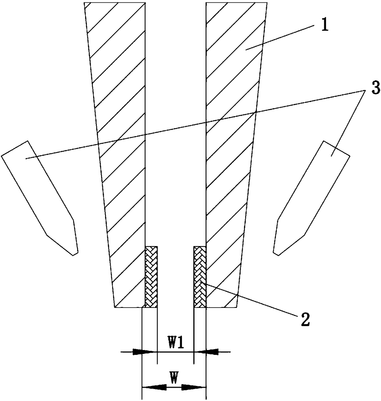
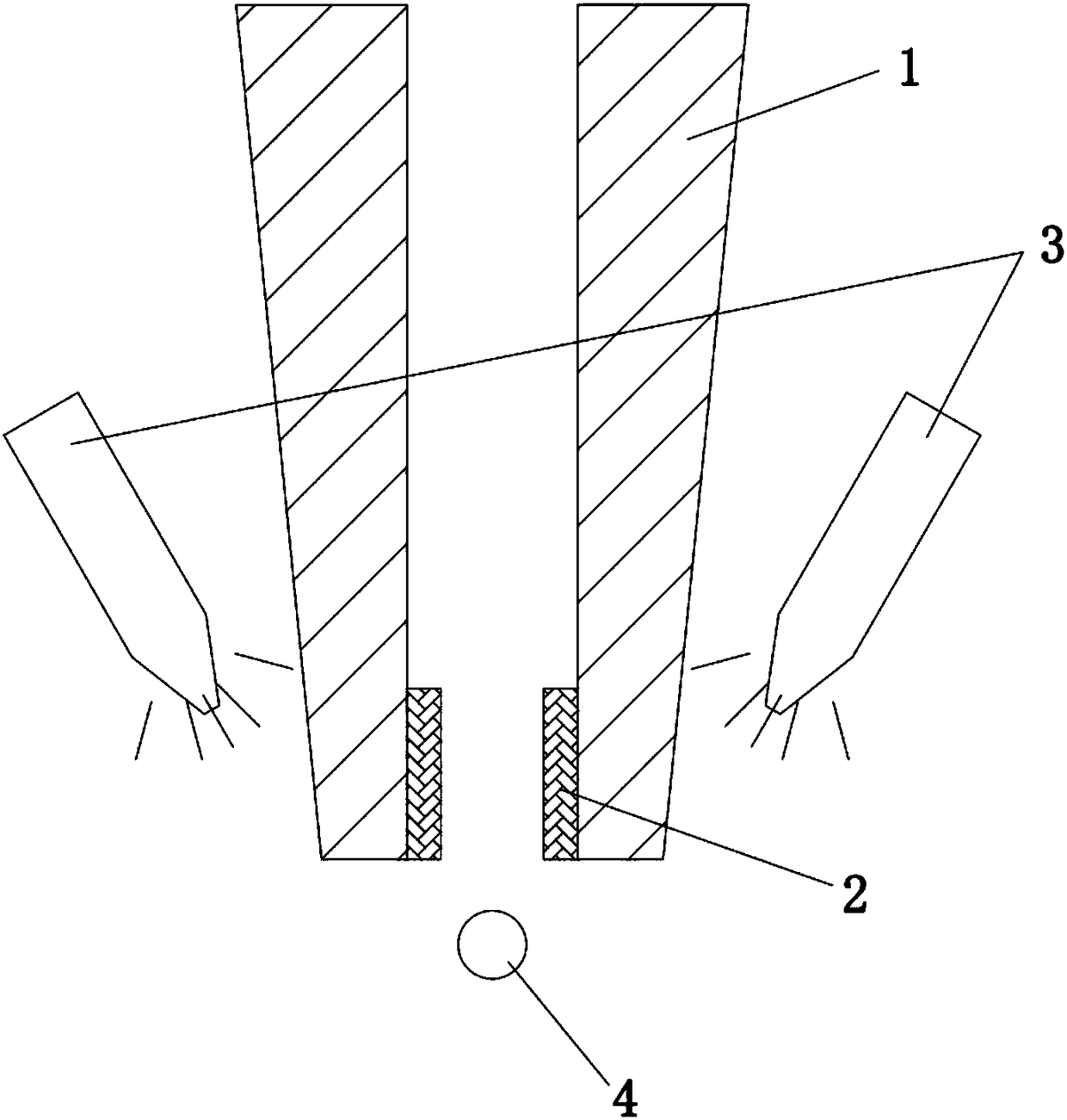
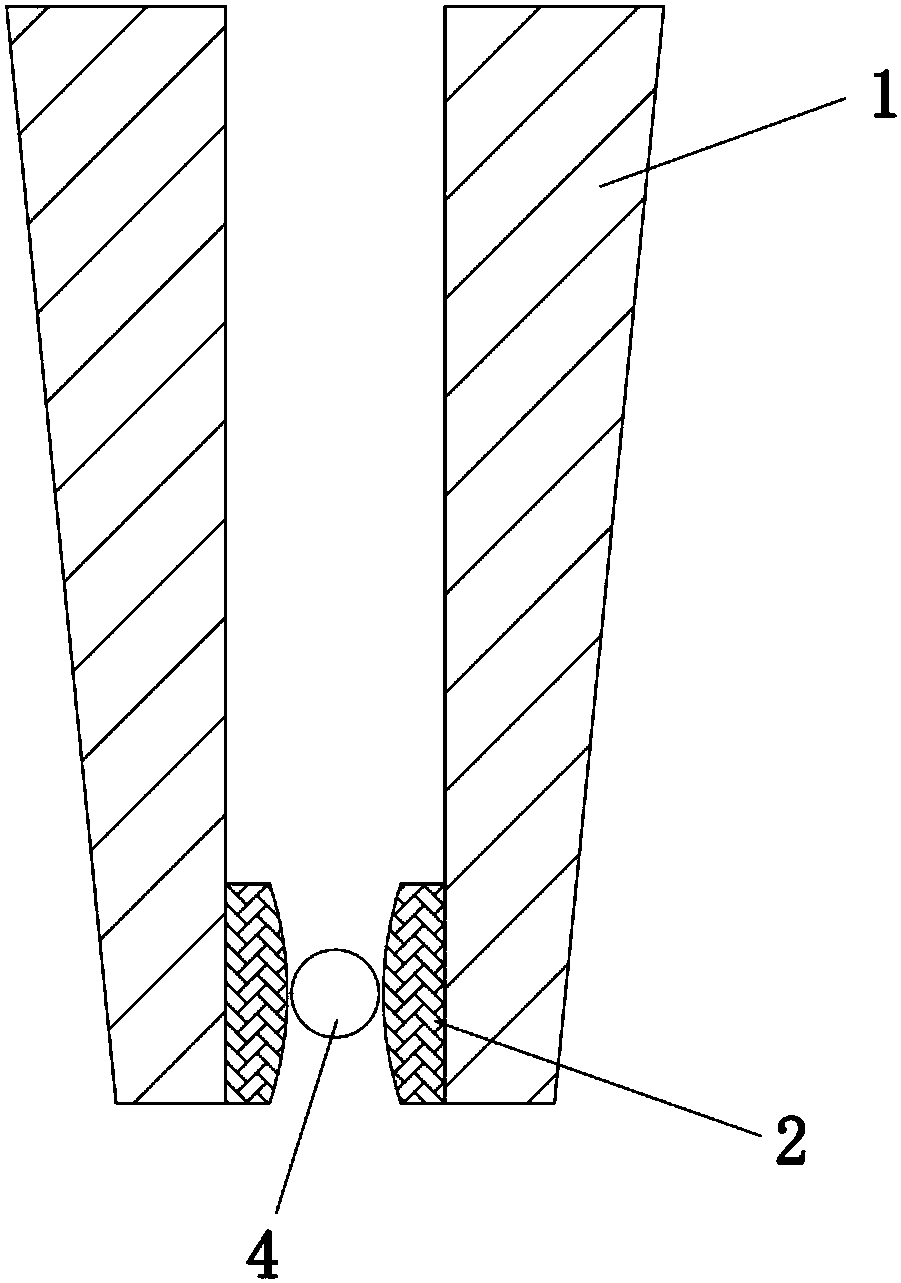
[0034] This embodiment proposes a cell capture device, such as figure 1 As shown, it includes a capillary 1 and a light source 3, wherein the inner wall of the orifice of the capillary 1 is provided with a photodeformable layer 2, and the inner diameter of the orifice is not less than the diameter of the cell 4 to be captured; the light source 3 is arranged on the outside of the capillary 1, and the light source 3 can The photodeformable layer 2 is irradiated through the capillary 1, and the photodeformabl...


PUM


Abstract

The invention relates to the technical field of cell separation, and discloses a cell capture device. The cell capture device comprises a capillary tube and a light source, wherein the inner wall of atube opening of the capillary tube is provided with a photoinduced deformation layer, and the inner diameter of the tube opening is not smaller than the diameter of to-be-captured cells; the light source is arranged on the outer side of the capillary tube, the light source can irradiate the photoinduced deformation layer through the capillary tube, and the photoinduced deformation layer deforms to make the inner diameter of the tube opening small after being irradiated. According to the cell capture device, the photoinduced deformation layer is arranged on the inner wall of the tube opening of the capillary tube, and the inner diameter of the tube opening is changed through the deformation of the photoinduced deformation layer, so that the capture of the to-be-captured cells is achieved,the production requirement that the diameter of the required capillary tube is smaller than the diameter of the to-be-captured cells is reduced, and therefore the processing difficulty and the processing cost are reduced; the photoinduced deformation layer is arranged at the capture position of the tube opening, so that the to-be-captured cells are protected to a certain extent, and the to-be-captured cells are prevented from being damaged.

Description

technical field [0001] The invention relates to the technical field of cell separation, in particular to a cell capture device. Background technique [0002] Single-cell level research has been widely used in single-cell PCR amplification, genome sequencing, and tissue engineering research. With the deepening of research, the effective separation of single tumor cells has become one of the urgent problems to be solved in the research of the molecular mechanism of tumor cell occurrence, targeted therapy of tumor cells, and microenvironmental interaction. [0003] The current common single cell isolation methods include the following: [0004] 1) Fluorescent flow cytometry separation method: This method can effectively obtain single cells, but it has high requirements on the performance of the cytometer and the instrument is expensive; [0005] 2) Laser microdissection: It can separate single cells from tissues, but it is not suitable for cell culture and expansion, and requ...

Claims


Application Information

Patent Timeline
IPC IPC(8): C12M1/12C12M1/00
CPCC12M23/16C12M23/22C12M31/02C12M37/00C12M47/04
Inventor 顾志鹏李重阳宋建军李建霖刘勇娥
Owner DONGGUAN HEC MEDICAL INTELLIGENT DEVICE R&D CO LTD
Features
  • R&D
  • Intellectual Property
  • Life Sciences
  • Materials
  • Tech Scout
  • Unparalleled Data Quality
  • Higher Quality Content
  • 60% Fewer Hallucinations
Learn More