A shipboard radar radome and its manufacturing method
A radome and manufacturing method technology, applied to antennas, antenna components, antennas suitable for movable objects, etc., can solve the problems of weak surface hydrophobicity and mildew resistance, poor wave transmission performance in high and wide frequency bands, and waterproof poor performance
- Summary
- Abstract
- Description
- Claims
- Application Information
AI Technical Summary
Problems solved by technology
Method used
Image
Examples
specific Embodiment approach 1
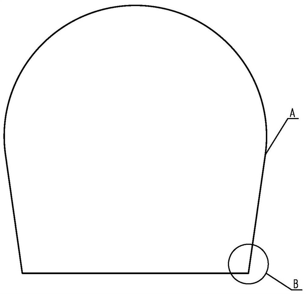
[0066] A kind of shipboard radar antenna is a shipboard radome with the overall structure of high and wide frequency band radar. ,Such as figure 2 Shown; during installation, bolts are used to fasten the connection between the flange of the radome and the base;
[0067] The spherical cap on the upper part of the radome and the lower cylinder (or cone) are the radar antenna wave-transparent zone A; the root of the cylinder (or cone) to the connecting flange is a non-wave-transparent structural reinforcement zone B;
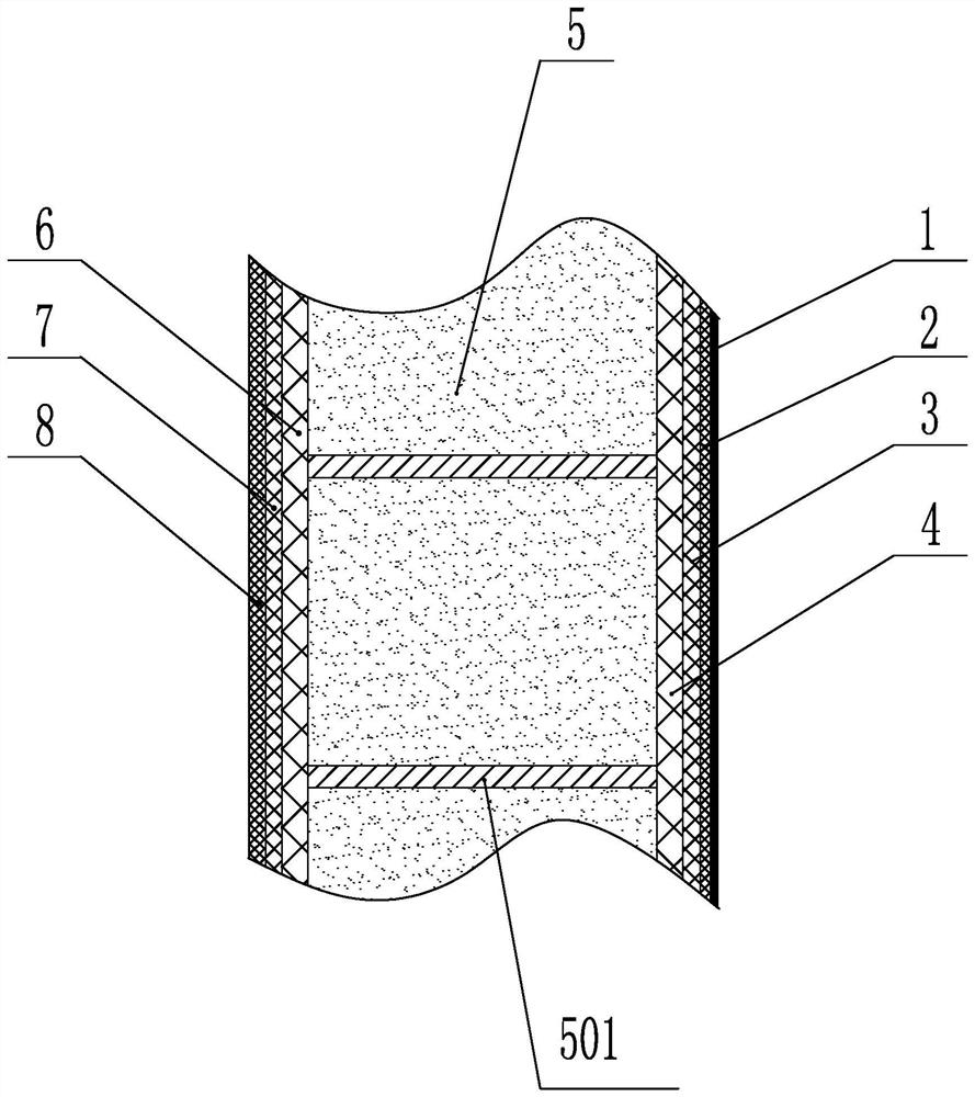
[0068] Such as image 3 As shown, the wave-transmitting area of the radar antenna is a composite material sandwich structure, and the cross-sectional material of the composite material sandwich structure sequentially includes: a super-hydrophobic coating 1, an outer surface wave-transparent paint coating 2, an outer surface Surface anti-aging layer 3, outer skin layer 4, structural foam core layer 5, inner skin layer 6, inner surface wave-transparent paint coa...
specific Embodiment approach 2
[0078] Specific implementation mode two: combining such as Figure 9 To describe this embodiment,
[0079] A method for manufacturing a shipboard radome, comprising the following steps:
[0080] The shape of the molding die D is the same as that of the radome C, and several (set to 4) resin injection ports 101 are evenly distributed on the cylindrical (or conical) edge away from the spherical cap on the molding die having the same shape as the radome. A plurality of (set to 8) resin outlets 102 are uniformly arranged at or near the junction of the spherical cap and the cylinder (or cone) of the molding mold, and several (set to 1) resin outlets 102 are arranged on the top of the spherical crown of the molding mold; The forming mold can be removed in the demoulding step after the product is formed; the forming mold has certain structural rigidity, precise size and shape, perfect sealing, pull-out characteristics and thermal deformation resistance required by product forming; ...
specific Embodiment approach 3
[0109] In the process of laying the outer skin reinforcement transition layer described in this embodiment, the high-strength fiber cloth is laid on the side of the radome wall from the radome connecting flange to the side of the radome wall, and laid until the radome wall is 200mm away from the edge of the flange. That is, the laying height of the transition zone is 200mm, and the laying thickness of the fiber cloth corresponding to the transition zone gradually changes from 4mm to 0.5mm.
[0110] Other steps and parameters are the same as in the second embodiment.
PUM
| Property | Measurement | Unit |
|---|---|---|
| thickness | aaaaa | aaaaa |
| viscosity | aaaaa | aaaaa |
| thickness | aaaaa | aaaaa |
Abstract
Description
Claims
Application Information
 - R&D
- Intellectual Property
- Life Sciences
- Materials
- Tech Scout
- Unparalleled Data Quality
- Higher Quality Content
- 60% Fewer Hallucinations
Browse by: Latest US Patents, China's latest patents, Technical Efficacy Thesaurus, Application Domain, Technology Topic, Popular Technical Reports.
© 2025 PatSnap. All rights reserved.Legal|Privacy policy|Modern Slavery Act Transparency Statement|Sitemap|About US| Contact US: help@patsnap.com


