Convex-concave meshing pure rolling spiral bevel gear mechanism for cross shaft transmission
A technology of spiral bevel gear and cross shaft, which is applied in the field of convex-concave meshing pure rolling spiral bevel gear mechanism, which can solve the problems of uncertain value of coincidence degree of transmission pair, inability to realize strict design of coincidence degree, and unfavorable load uniform distribution, etc.
- Summary
- Abstract
- Description
- Claims
- Application Information
AI Technical Summary
Problems solved by technology
Method used
Image
Examples
Embodiment 1
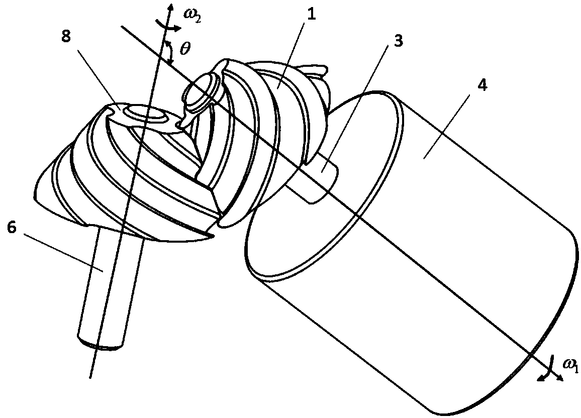
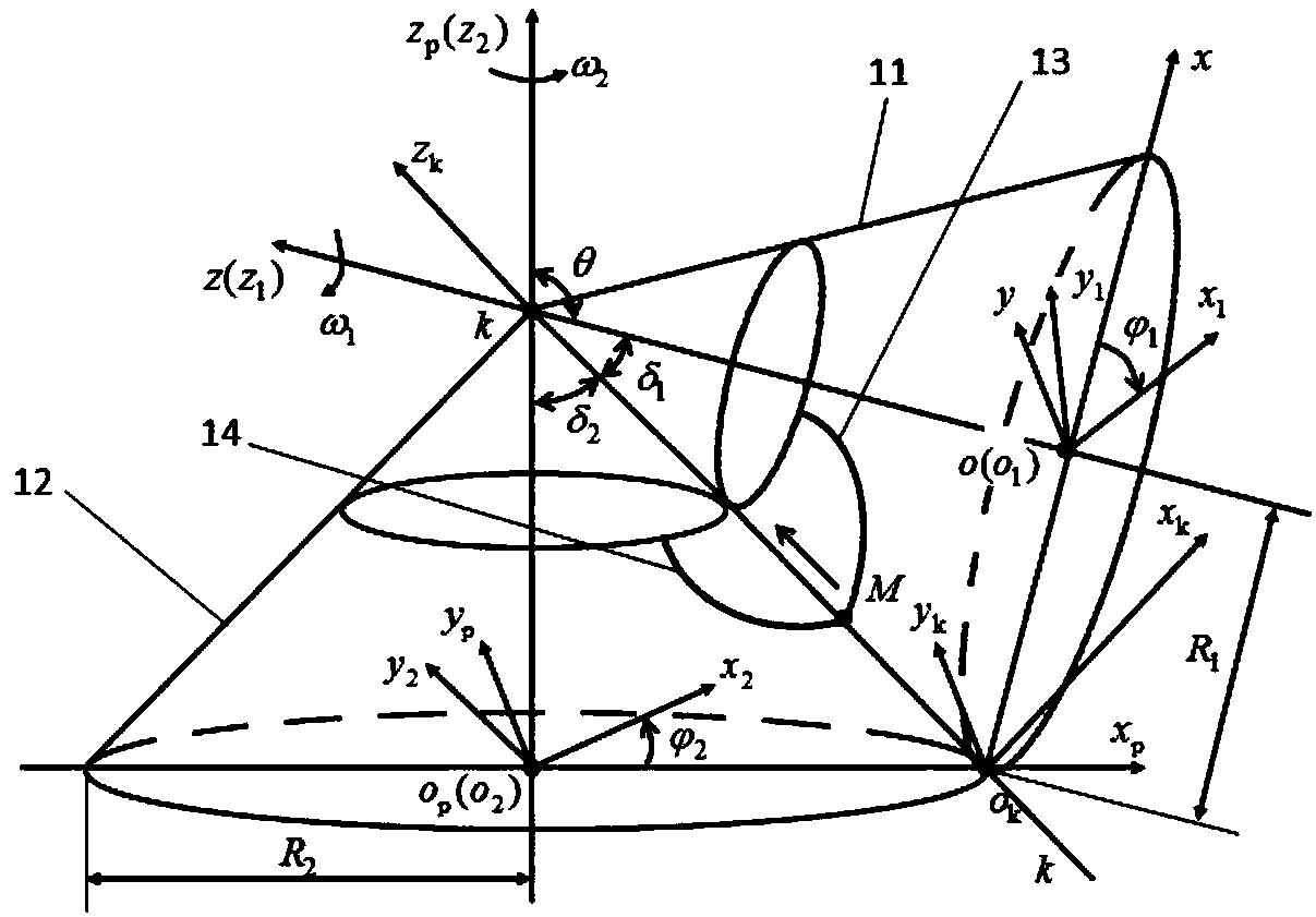
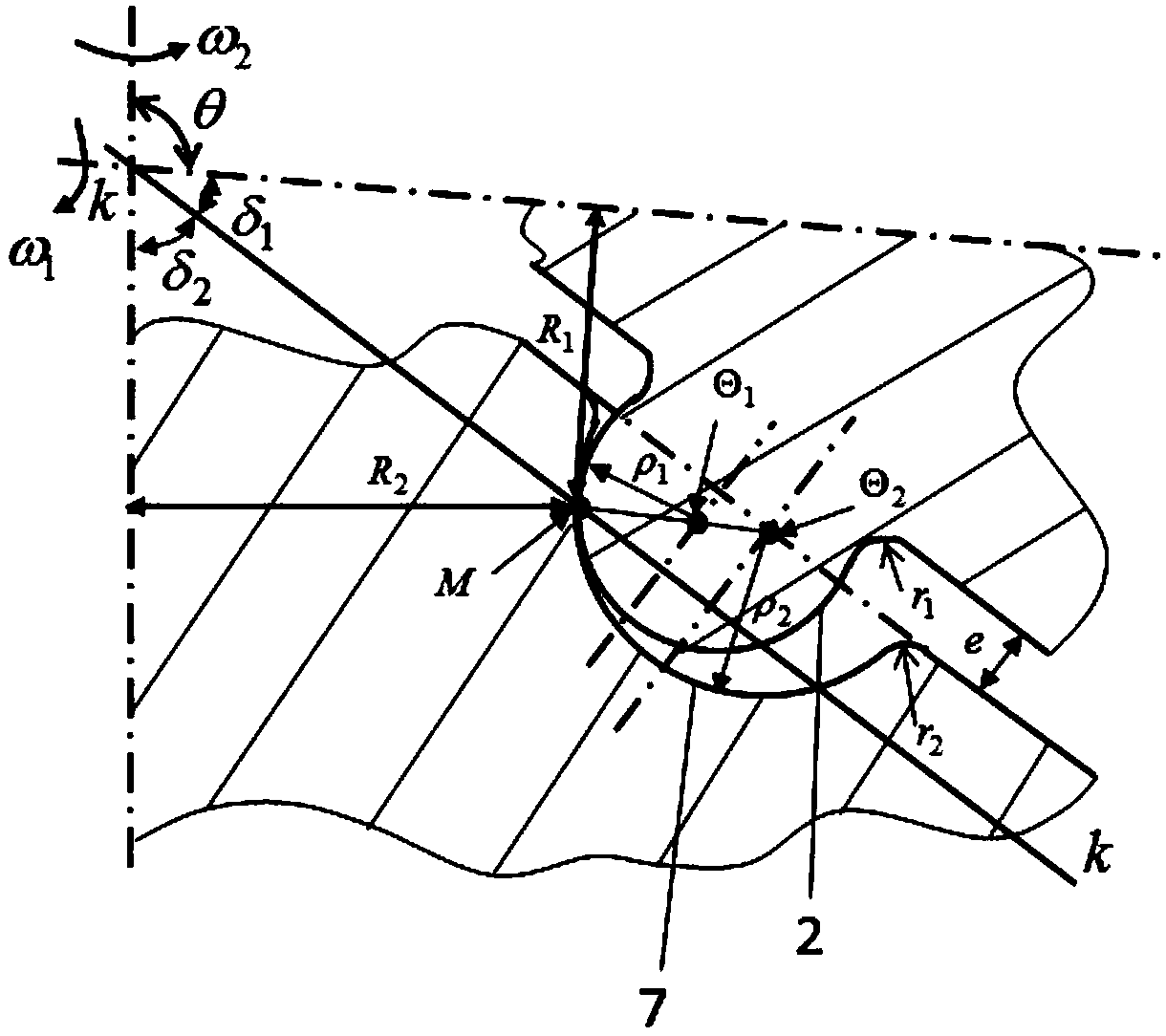
[0115] Embodiment 1: The present invention provides a convex-concave meshing pure rolling spiral bevel gear mechanism for cross shaft transmission, which is applied to the transmission with a transmission ratio of 1 between two cross shafts in the plane, and its structure is as follows figure 1 As shown, it includes a small wheel 1 and a large wheel 8. The small wheel 1 and the large wheel 8 form a pair of transmission pairs. The small wheel 1 is connected to the input shaft 3, and the large wheel 8 is connected to the output shaft 6, that is, the large wheel 8 is connected to the output shaft 6 through the output shaft 6. The driven load is connected; the axes of the small wheel 1 and the large wheel 8 intersect, and the angular velocity vector angle between the small wheel 1 and the large wheel 8 is θ, and θ=2π / 3 radians (rad) in this example. figure 2 It is a schematic diagram of the spatial meshing coordinate system of the convex-concave meshing pure rolling spiral bevel g...
Embodiment 2
[0219] Embodiment 2: The convex-concave meshing pure rolling spiral bevel gear mechanism of the present invention for cross shaft transmission is applied to the speed-up transmission between two vertical cross shafts, at this time θ=π / 2 radians (rad). Such as Figure 10 As shown, the large wheel 8 is used to connect the input shaft 3, and the small wheel 1 is connected to the output shaft 6, that is, the small wheel 1 is connected to the driven load through the output shaft 6; the axes of the small wheel 1 and the large wheel 8 are perpendicular to each other, and at this time they The included angle of angular velocity is θ=π / 2(rad) radians. In this embodiment, there are eight spiral arc grooves 7 on the bull wheel 8, and four spiral arc teeth 2 on the small wheel 1. When the input shaft 3 drives the bull wheel 8 to rotate, the design coincidence degree ε=4 / 3. Because when the big wheel 8 and the small wheel 1 are installed, the spiral circular arc groove 7 on the large whee...
PUM
 Abstract
Description
Claims
Application Information
 - R&D
- Intellectual Property
- Life Sciences
- Materials
- Tech Scout
- Unparalleled Data Quality
- Higher Quality Content
- 60% Fewer Hallucinations
Browse by: Latest US Patents, China's latest patents, Technical Efficacy Thesaurus, Application Domain, Technology Topic, Popular Technical Reports.
© 2025 PatSnap. All rights reserved.Legal|Privacy policy|Modern Slavery Act Transparency Statement|Sitemap|About US| Contact US: help@patsnap.com


