Design Method of Orbital Angular Momentum Vortex Electromagnetic Wave Generator

A technology of vortex electromagnetic wave and orbital angular momentum, applied in electrical components, antennas, geometric CAD, etc., can solve problems such as the complex structure of the rotating phase plate, achieve low price, tight connection, and reduce industrial manufacturing costs

Active Publication Date: 2020-09-15
XIDIAN UNIV
View PDF4 Cites 0 Cited by
  • Summary
  • Abstract
  • Description
  • Claims
  • Application Information

AI Technical Summary

Problems solved by technology

[0004] In order to solve the deficiencies of the prior art, the object of the present invention is to provide a design method of an orbital angular momentum vortex electromagnetic wave generator, which can not only solve the above-mentioned problem of complex structure of the rotating phase plate, but also greatly reduce the The divergence angle of the beam increases the transmission distance, and at the same time, it is easier to install, fix and use the orbital angular momentum vortex electromagnetic wave generator

Method used


Image

  • Design Method of Orbital Angular Momentum Vortex Electromagnetic Wave Generator
  • Design Method of Orbital Angular Momentum Vortex Electromagnetic Wave Generator
  • Design Method of Orbital Angular Momentum Vortex Electromagnetic Wave Generator

Examples


Embodiment Construction

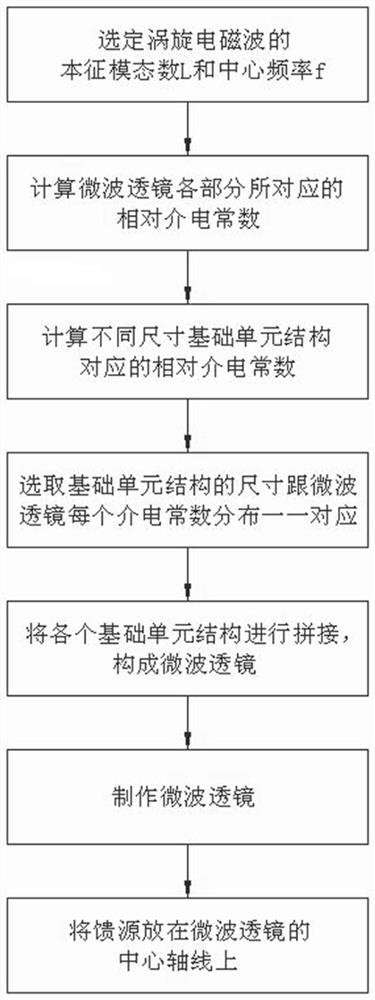
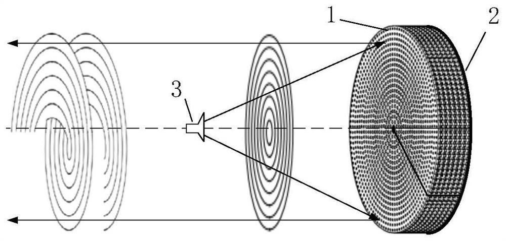
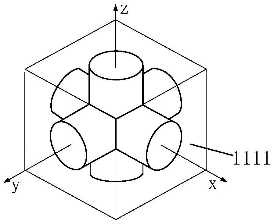
[0040] The design method of the orbital angular momentum vortex electromagnetic wave generating device provided by the present invention, the overall idea is: through the space transformation theory, the discrete rotating phase plate is equivalently transformed into a cylindrical lens, and the size of each basic unit of the microwave lens is changed to realize The change of the relative permittivity of each basic unit changes the propagation path of the incident plane wave in the microwave lens to achieve phase compensation. After being reflected by the metal reflector, the second phase compensation is realized, and the vortex is generated after two phase compensations. electromagnetic waves.

[0041] Taking the design of an orbital angular momentum vortex electromagnetic wave generating device capable of generating vortex electromagnetic waves with a center frequency of 10 GHz and an eigenmode of 1 as an example, the present invention will be described in detail below in conju...


PUM


Abstract

The invention discloses an orbit angular momentum vortex electromagnetic wave generation apparatus design method comprising the following steps: step 1, a cylindrical microwave lens is designed and relative dielectric constants corresponding to basic unit structures of different sizes are calculated; step 2, the microwave lens is formed; step 3, the microwave lens is made; step 4, the microwave lens and a feed source are placed. The beneficial effects of the method are that: (1) compared with a discrete rotating phase plate, the microwave lens disclosed in the invention is advantaged by tightstructure connection, easy fixation, portability, easy usage, a small divergence angle of a wave beam of generated vortex electromagnetic waves, concentrated directions, and large transmission distance; (2) the microwave lens of the present invention allows the bandwidth of a transmitting antenna to be widened to 7 GHz to 13 GHz; (3) all-dielectric material is adopted in the microwave lens of thepresent invention and is low in energy consumption and high in corrosion resistance; (4) the microwave lens is made via use of 3D printing technology, and low price of the technology can help greatlyreduce industrial manufacturing costs.

Description

technical field [0001] The invention relates to a design method of a device, in particular to a design method of an orbital angular momentum vortex electromagnetic wave generator, and belongs to the technical fields of transformation optics and wireless communication. Background technique [0002] Common communication services in wireless systems are usually based on linear momentum in the electromagnetic (EM) domain, typically employing communication schemes that are modulated based on the phase, frequency, or amplitude of the electromagnetic signal. With the rapid development of wireless communication technology, the spectrum that can be allocated by each communication system is becoming more and more crowded, and the shortage of frequency band resources is becoming an important factor affecting the development of wireless communication technology. In recent years, vortex electromagnetic waves capable of carrying orbital angular momentum (OAM) have received great attention...

Claims


Application Information

Patent Timeline
Patent Type & Authority Patents(China)
IPC IPC(8): H01Q15/08H01Q19/06H01Q19/10G06F30/17
CPCG06F30/17H01Q15/08H01Q19/06H01Q19/104
Inventor 衣建甲冯瑞曹雪琦孟颖繁黄晋鹏梁晓涓张海林
Owner XIDIAN UNIV
Why Eureka
Try Eureka