Fast automatic mode locking method covering multi-state pulse recognition

An automatic mode-locking and state recognition technology, which is applied to laser parts, electrical components, lasers, etc., can solve problems such as high algorithm complexity, large amount of calculation, and complex mode-locking recognition

Active Publication Date: 2018-09-14
杭州爱鸥光学科技有限公司
View PDF9 Cites 7 Cited by
  • Summary
  • Abstract
  • Description
  • Claims
  • Application Information

AI Technical Summary

Problems solved by technology

However, the polarization control of NPE-based passive mode-locked lasers has always been a problem, especially when multiple output states are desired (such as harmonic mode-locking, Q-switching, etc.), the accuracy requirements for polarization control will be greatly increased and in When performing state switching, it is necessary to repeatedly adjust the polarization state, which is almost impossible for manual operation
[0005] In order to solve the above problems, in recent years, a small number of experiments using electronically controlled polarization to achieve automatic mode locking have been reported. U.Andral et al. from the University of Burgundy and R.I.Woodward et al. , combined with electronically controlled polarization technology, automatic mode locking is realized, but the experimental structure of the former is cumbersome, requiring two electrical polarization controllers (Electrical Polarization Controller, EPC), 6-way voltage control; the identification of mode locking in the latter is complicated, requiring Simultaneously use time domain, frequency domain and spectral information to comprehensively identify
In addition, the complexity of the GA algorithm is high, which is not conducive to real-time, and the amount of calculation is large. The time-consuming of model locking in the two schemes is about 30 minutes.

Method used


Image

  • Fast automatic mode locking method covering multi-state pulse recognition
  • Fast automatic mode locking method covering multi-state pulse recognition
  • Fast automatic mode locking method covering multi-state pulse recognition

Examples


Embodiment Construction

[0040] The following describes several preferred embodiments of the present invention with reference to the accompanying drawings, so as to make the technical content clearer and easier to understand. The present invention can be embodied in many different forms of embodiments, and the protection scope of the present invention is not limited to the embodiments mentioned herein.

[0041] In the drawings, components with the same structure are denoted by the same numerals, and components with similar structures or functions are denoted by similar numerals. The size and thickness of each component shown in the drawings are shown arbitrarily, and the present invention does not limit the size and thickness of each component. In order to make the illustration clearer, the thickness of parts is appropriately exaggerated in some places in the drawings.

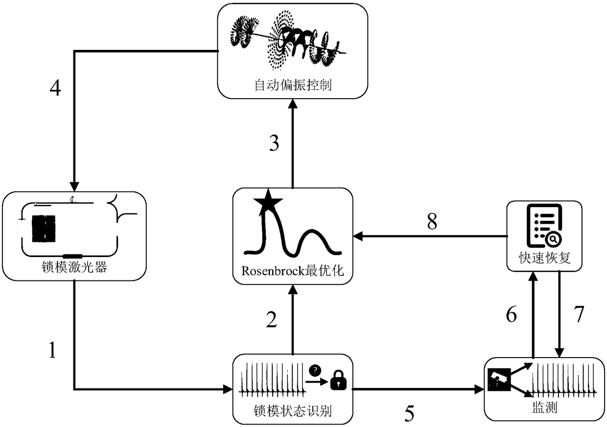
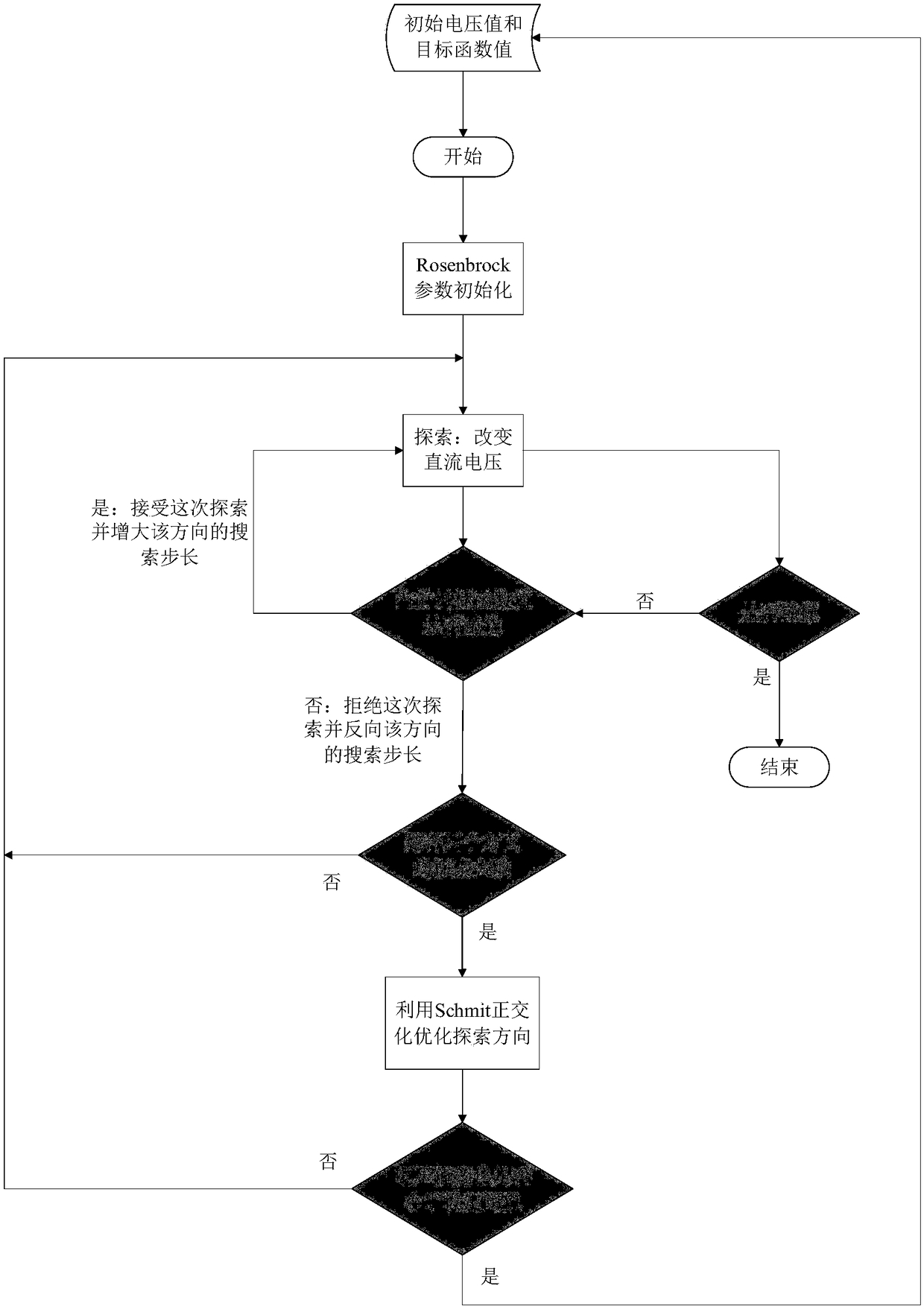
[0042] The invention utilizes the EPC module, is based on the Rosenbrock optimization method, and combines multi-state pulse identi...


PUM


Abstract

The invention discloses a fast automatic mode locking method covering multi-state pulse recognition and belongs to the mode-locked laser and automatic control field. The method include the following steps that: after being subjected to photoelectric conversion and high-speed sampling, the output signals of a mode-locked laser are used for mode locking state recognition; if the result of the mode locking state recognition is a mode unlocked state, optimization is carried out; an adjusted polarization state value is inputted to a digital-to-analog converter from a computing center through a serial communication protocol according to an optimization algorithm, and is converted into four direct-current voltages; the outputted four direct-current voltages drive an electronically controlled polarization controller in the mode-locked laser, so that automatic polarization control can be realized; if the result of the mode locking state recognition is a mode-locked state, a monitoring mode is enabled; and if locking failure is detected, and rapid mode-locking resuming is successful, the monitoring mode is resumed. With the method adopted, the problem of polarization control in a passive mode-locked laser based on nonlinear polarization evolution is solved, and the mode-locked laser can quickly and automatically lock a mode and stably work under a target state.

Description

technical field [0001] The invention relates to the field of mode-locked lasers and automatic control, in particular to a fast automatic mode-locking method covering multi-state pulse identification. Background technique [0002] Mode-locked lasers are one of the most cutting-edge and active research directions in the field of optoelectronic technology today, and they are also the basis and starting point for the research of ultrafast optical systems. Many studies in physics, chemistry, biology, materials and information science and other disciplines use ultrashort pulses as a basic tool to continuously reveal new ultrafast change processes and intuitively explore the laws of motion of matter in the microscopic world. Mode-locked lasers can generate pulses with high pulse energy and narrow pulse width, so they are widely used in material processing and fabrication, microscopy, biological imaging, distance measurement, dimension measurement, clock and synchronization, optical...

Claims


Application Information

Patent Timeline
Patent Type & Authority Applications(China)
IPC IPC(8): H01S3/11
CPCH01S3/1112
Inventor 义理林蒲国庆张力胡卫生
Owner 杭州爱鸥光学科技有限公司
Why Eureka
Try Eureka