
Feedback circuit and method for compensating line loss voltage

A technology of feedback circuit and compensation line, which is applied in the direction of adjusting electrical variables, control/regulation systems, instruments, etc., can solve problems such as abnormal use of electrical load equipment, insufficient power supply voltage, etc., to achieve increased output voltage, accurate voltage value, The effect of low implementation cost

Active Publication Date: 2018-09-18
NINGBO POLYTECHNIC
View PDF5 Cites 2 Cited by
  • Summary
  • Abstract
  • Description
  • Claims
  • Application Information

AI Technical Summary

Problems solved by technology

[0003] When the switching power supply is in use, it is necessary to connect the output positive and negative poles of the switching power supply to the electrical load equipment through external wires and connectors. Since the external wires have internal resistance and the connectors have contact resistance, when the current flows through them The loss voltage is the line loss voltage. The line loss voltage causes the voltage at both ends of the electrical load equipment to be lower than the output voltage of the switching power supply. The voltage at the terminal will be much lower than the output voltage of the switching power supply, so that the actual power supply voltage supplied to the electrical load equipment is insufficient, and it is easy to cause the electrical load equipment to not work normally.

Method used


Image

  • Feedback circuit and method for compensating line loss voltage
  • Feedback circuit and method for compensating line loss voltage
  • Feedback circuit and method for compensating line loss voltage

Examples


Embodiment 1

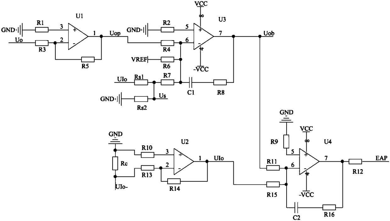
[0044] This embodiment provides a feedback circuit for compensating line loss voltage, such as Figure 1 to Figure 2 As shown, the circuit includes:

[0045] The current detection module is used to detect the output current Io of the feedback circuit in real time through the sampling resistor Rc;

[0046] The voltage outer loop feedback module is used to introduce the line loss voltage Us calculated according to the preset line loss resistance Rs and the output current Io, combine the line loss voltage Us, the reference voltage VREF and the voltage feedback value Uop on the load, and output the external Loop feedback voltage deviation Uob;

[0047] The output current inner loop feedback module is used to combine the received outer loop feedback voltage deviation Uob with the output voltage UIo corresponding to the output current, and output the inner loop feedback circuit voltage EAP signal to the power chip.

[0048] Further, the current detection module includes: a resisto...

Embodiment 2

[0078] This embodiment provides a switching power supply for new energy vehicles. The input voltage is DC230-370V, and the output is DC14.2V / 70A. It is a typical switching power supply with high voltage and high current output. The topology adopts phase-shifting full-bridge current doubling synchronous rectification. circuits, such as image 3 As shown, the detailed feedback circuit is as Figure 4 As shown, the power chip adopts UCC28950PW, and its minimum system is as follows Figure 5 shown.

[0079] like image 3 In the topological structure, phase-shifted full-bridge current doubling synchronous rectification topology is used as the power stage circuit, and clamping diodes are used in the primary stage. The four MOSFET models of the primary stage are STP25NM60N, and the models of clamping diodes D1 and D2 are STTH8R06D. Synchronous rectification 2 MOSFET models use IRFP4368, transformer T1 uses PQ40 magnetic core, inductor L2 uses EI40 magnetic core, inductors L1 and L...


PUM


Abstract

The invention discloses a feedback circuit for compensating line loss voltage. The feedback circuit is used for compensating the line loss voltage caused by line loss resistance in a power output circuit. The circuit comprises a current detection module, a voltage outer loop feedback module and an output current inner loop feedback module; the current detection module is used for detecting outputcurrent Io of the feedback circuit in real time through a sampling resistor Rc; the voltage outer loop feedback module is used for introducing the line loss voltage Us calculated according to preset line loss resistance Rs and the output current Io, combining the line loss voltage Us, reference voltage VREF and a voltage feedback value Uop on a load and outputting an outer loop feedback voltage deviation Uob; the output current inner loop feedback module is used for combining the received outer loop feedback voltage deviation Uob with output voltage UIo corresponding to the output current andoutputting an inner loop feedback circuit voltage EAP signal to a power chip. The line loss voltage is compensated by increasing an expected value of the output voltage, the voltage which is output bya switch power supply and connected to a load terminal is more accurate, and meanwhile the maximum value of the output current can be limited for short circuit protection.

Description

technical field [0001] The invention relates to the field of switching power supplies, in particular to a feedback circuit and a feedback method for compensating line loss voltage. Background technique [0002] Switching power supply is an important power conversion device, which is indispensable in all walks of life. [0003] When the switching power supply is in use, it is necessary to connect the output positive and negative poles of the switching power supply to the electrical load equipment through external wires and connectors. Since the external wires have internal resistance and the connectors have contact resistance, when the current flows through them The loss voltage is the line loss voltage. The line loss voltage causes the voltage at both ends of the electrical load equipment to be lower than the output voltage of the switching power supply. The voltage at the terminal will be much lower than the output voltage of the switching power supply, so that the actual ...

Claims


Application Information

Patent Timeline
Patent Type & Authority Applications(China)
IPC IPC(8): G05F1/56
CPCG05F1/561
Inventor 刘珺
Owner NINGBO POLYTECHNIC
Learn More