Dynamic wireless automatic charging new energy vehicle

A new energy vehicle, automatic charging technology, applied in electric vehicles, electric vehicle charging technology, charging stations, etc., can solve the problems of inability to store a large amount of electric energy in batteries, electromagnetic radiation harming the human body, and inconvenience.

Active Publication Date: 2018-09-21
朱幕松
View PDF4 Cites 1 Cited by
  • Summary
  • Abstract
  • Description
  • Claims
  • Application Information

AI Technical Summary

Problems solved by technology

At present, the charging method of new energy vehicles mainly relies on widely installed charging piles. However, the charging piles cannot store a large amount of electric energy for the battery in a short period of time, and manual operation is required to connect the charger with the car battery. As a result, car charging not only takes up space , inconvenient, and a waste of time
Dynamic wireless charging is a technology that uses electromagnetic fields or electromagnetic waves for energy transfer, that is, the primary transmitting coil is placed inside the road, and the secondary receiving coil is placed inside the car, and the power transmission is performed through the coupling of high-frequency magnetic fields, making new energy vehicles Charging while driving, because it is fully insulated to avoid the risk of high-voltage electric shock, fully sealed to avoid the risk of short circuit and leakage, and can adapt to a variety of harsh environments and weather, it has no mechanical wear, maintenance-free, and is convenient for automatic operation, but the existing new Dynamic wireless charging devices for energy vehicles have low power conversion efficiency, complex structure, high cost, and problems such as leakage of electromagnetic radiation that can harm the human body.

Method used


Image

  • Dynamic wireless automatic charging new energy vehicle
  • Dynamic wireless automatic charging new energy vehicle
  • Dynamic wireless automatic charging new energy vehicle

Examples


Embodiment Construction

[0020] Further description will be made below in conjunction with accompanying drawings.

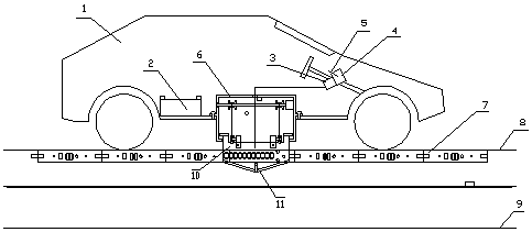
[0021] exist figure 1 In the overall right-view structural diagram of the charging state of the dynamic wireless automatic charging new energy vehicle shown, the dynamic wireless automatic charging new energy vehicle is any pure electric vehicle 1, and the battery pack 2 and the front cab are arranged in the rear of the pure electric vehicle. The instrument panel is provided with an intelligent control box 3, an intelligent control module and an intelligent charging module are arranged in the intelligent control box, the output end of the intelligent charging module is connected to the storage battery pack, an IC card reader 4 is arranged on the right side of the intelligent control box, and the IC card is read Ic card 5 is inserted into the card holder, a rectangular mounting opening is set in the middle of the chassis of the pure electric vehicle, and a chassis receiving motor 6 is ins...


PUM


Abstract

Provided is a dynamic wireless automatic charging new energy vehicle. Long-distance magnetic field tanks are formed by left original side power supply plates and right original side power supply plates, new energy vehicles are arranged on chassis powered machines and auxiliary side powered plates, the auxiliary side powered plates are coupled between the left original side power supply plates andthe right original side power supply plates, and the auxiliary side powered plates conduct medium-frequency wireless electric transmission in the electromagnetic induction in a continuous dynamic closed magnetic flux state; under the control of an intelligent control module, the auxiliary side powered plates conduct automatic notch cutting, automatic coupling positioning, power utilization automatic recognizing and billing, left-right range-exceeding automatic recovering and driving magnetic field tank tail end automatic recovering, the auxiliary side powered plates automatically adjust the horizontal angle and the left-right position in a case, the upper end of the magnetic field tank is flush with a pavement, the parallel width of the magnetic field tank is smaller than 20 mm, and the lower side of the magnetic field tank is provided with a sewer; the dynamic wireless automatic charging new energy vehicle does not occupy the pavement and does not influence the traffic or the city appearance, the six long-distance magnetic field tanks of an urban road are changed into a super charging field, and reasonable power supplying and reasonable billing are automatically conducted on eachvehicle.

Description

technical field [0001] The invention relates to a new energy vehicle, specifically, a dynamic wireless automatic charging new energy vehicle. Background technique [0002] my country's new energy vehicles are mainly hybrid vehicles and pure electric vehicles. The charging problem of these two types of vehicles has always been the main obstacle to the development of new energy vehicles. At present, the charging method of new energy vehicles mainly relies on widely installed charging piles. However, the charging piles cannot store a large amount of electric energy for the battery in a short period of time, and manual operation is required to connect the charger with the car battery. As a result, car charging not only takes up space , inconvenient, and a waste of time. Dynamic wireless charging is a technology that uses electromagnetic fields or electromagnetic waves for energy transfer, that is, the primary transmitting coil is placed inside the road, and the secondary receiv...

Claims


Application Information

Patent Timeline
Patent Type & Authority Applications(China)
IPC IPC(8): B60L11/18
CPCB60L53/12B60L53/30B60L53/37B60L53/38B60L53/665Y02T10/70Y02T10/7072Y02T90/12Y02T90/14Y02T90/16
Inventor 朱幕松
Owner 朱幕松
Why Eureka
Try Eureka