An optical polarizer and a method for adjusting its asymmetric transmission characteristics
An asymmetric transmission and polarizer technology, which is applied in optics, polarizing elements, optical elements, etc., can solve the problems that asymmetric transmission characteristics cannot be changed, achieve strong promotion and application value, improve detection sensitivity, and make easy preparation
- Summary
- Abstract
- Description
- Claims
- Application Information
AI Technical Summary
Problems solved by technology
Method used
Image
Examples
Embodiment 1
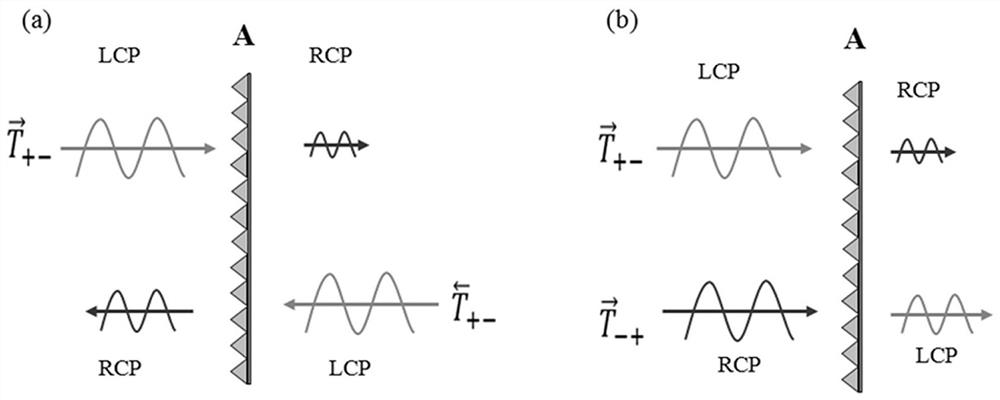
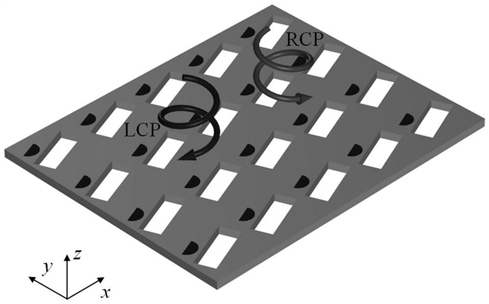
[0041] Such as figure 2 and image 3As shown, a metal optical polarizer in this embodiment includes a base layer and a planar structure, and the planar structure is formed by connecting a plurality of nano-period units 10 with the same structure in a rectangular periodic array. The optical polarizer of this embodiment is a planar structure with planar chirality, which can produce different polarization conversion rates for different circularly polarized lights. Strong promotion and application value.
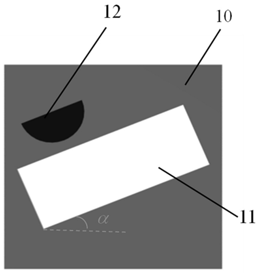
[0042] Such as image 3 As shown, the nano-period unit 10 is a rectangular block, and each period unit 10 contains a structural unit. The structural unit is composed of a rectangular hole 11 and a semicircular hole 12. The arc of the semicircular hole 12 and the rectangular hole The long sides of the 11 are separated or tangent, the diameter of the semicircular hole 12 is parallel to the long side of the rectangular hole 11, each nano-period unit 10 is made of noble metal ma...
Embodiment 2
[0048] Based on the structure of the optical polarizer in Embodiment 1, this embodiment discloses a method for adjusting the asymmetric transmission characteristics of the optical polarizer, comprising the following steps:
[0049] Step 1. At room temperature, place the optical polarizer in a closed device filled with hydrogen, add the catalyst palladium, and let it stand for more than 30 minutes. The metal Mg filled in the semicircular hole 12 undergoes a hydrogenation reaction with hydrogen to generate MgH 2 , which is equivalent to the medium, so that the structure of the optical polarizer changes, and its asymmetric transmission characteristics change accordingly;
[0050] Step 2, at room temperature, place the hydrogenated optical polarizer in an oxygen environment, MgH 2 An oxidative dehydrogenation reaction occurs, the metal filled in the semicircular hole 12 is reduced to metal Mg, and the asymmetric transmission characteristics of the optical polarizer are restored to...
Embodiment 3
[0060] The optical polarizer in this embodiment is a planar structure with planar chirality, which can produce different polarization conversion rates for different circularly polarized light, and achieve the purpose of adjusting the conversion characteristics of circularly polarized light without re-preparation.
[0061] Based on the optical polarizer structure in Example 1, before and after the property conversion of the filler metal Mg, a simulation calculation simulation experiment was performed by using the three-dimensional finite element method (FEM) calculation software COMSOL Multiphysics. The specific setting parameters are as follows:
[0062] The long side of the rectangular hole 11 is 520 nm, and the short side is 200 nm; the radius of the semicircular hole 12 is 100 nm; the vertical distance between the arc side of the semicircular hole 12 and the long side of the rectangular hole 11 is 5 nm ; The length of the nano-periodic unit 10 is 630 nm × width 630 nm × thi...
PUM
| Property | Measurement | Unit |
|---|---|---|
| thickness | aaaaa | aaaaa |
| transmittivity | aaaaa | aaaaa |
Abstract
Description
Claims
Application Information
 - R&D
- Intellectual Property
- Life Sciences
- Materials
- Tech Scout
- Unparalleled Data Quality
- Higher Quality Content
- 60% Fewer Hallucinations
Browse by: Latest US Patents, China's latest patents, Technical Efficacy Thesaurus, Application Domain, Technology Topic, Popular Technical Reports.
© 2025 PatSnap. All rights reserved.Legal|Privacy policy|Modern Slavery Act Transparency Statement|Sitemap|About US| Contact US: help@patsnap.com


