Optical polarizer capable of dynamically adjusting AT (asymmetric transmission) signal and using method of optical polarizer

An asymmetric transmission and dynamic adjustment technology, applied in the direction of the polarizing element, can solve the problem that the relative size of the polarization conversion of polarized light cannot be adjusted, and achieve the effect of simple structure, fast speed and high efficiency

Active Publication Date: 2018-09-14
西安柯莱特信息科技有限公司
View PDF11 Cites 0 Cited by
  • Summary
  • Abstract
  • Description
  • Claims
  • Application Information

AI Technical Summary

Problems solved by technology

[0011] In order to solve the problem that the relative size of the polarization conversion of polarized light cannot be adjusted in the prior art, the present invention provides an optical polarizer that can dynamically adjust asymmetric transmission signals and its use method. The structure can be adjusted by nanometer The relative effective length of the metal rod is used to achieve the purpose of adjusting the size and position of the asymmetric transmission mode, and the structure can be integrally formed, and the asymmetric transmission of the structure can be realized only by hydrogen absorption or dehydrogenation according to the need in the later use Signal conditioning, preparation and use methods are simple and convenient, easy to operate

Method used


Image

  • Optical polarizer capable of dynamically adjusting AT (asymmetric transmission) signal and using method of optical polarizer
  • Optical polarizer capable of dynamically adjusting AT (asymmetric transmission) signal and using method of optical polarizer
  • Optical polarizer capable of dynamically adjusting AT (asymmetric transmission) signal and using method of optical polarizer

Examples


Embodiment 1

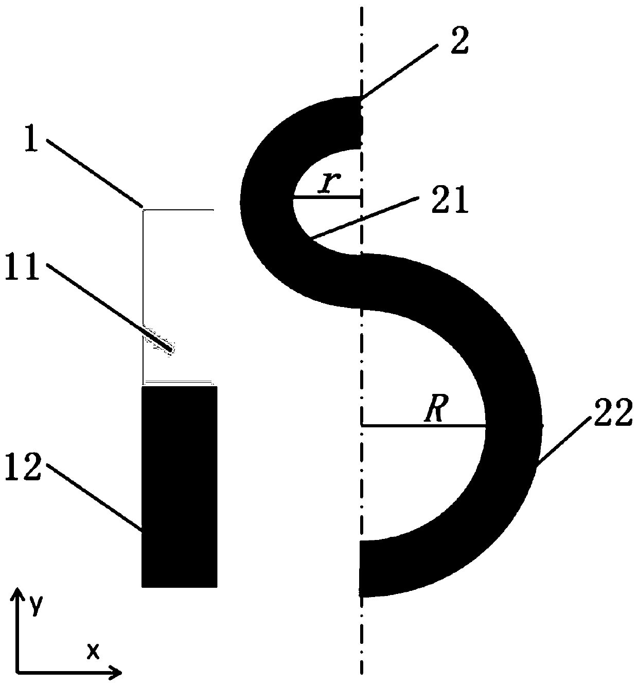
[0044] like figure 2 and image 3 The shown optical polarizer that can dynamically adjust asymmetric transmission signals includes a single-layer chiral structure composed of multiple periodic units with the same structure arranged in a rectangular periodic array, and each periodic unit contains a metal nanostructure unit, The metal nanostructure unit is composed of a metal nanorod 1 and an "S"-shaped metal nanostructure 2 connected through ports, the metal nanorod 1 and the "S"-shaped metal nanostructure 2 are located on the same plane, and the metal nanorod 1 is composed of the first The block 11 and the second component block 12 are connected, the first component block 11 is made of metal magnesium material, the second component block 12 and the "S" shaped metal nanostructure 2 are made of noble metal material.

[0045] In this embodiment, the optical polarizer is a planar periodic structure composed of two simple structural metal nanorods and an "S"-shaped metal nanostru...

Embodiment 2

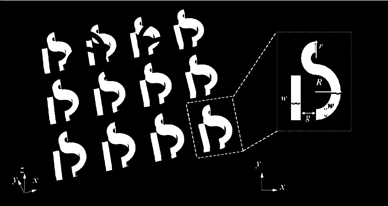
[0047] like figure 2 As shown, the metal nanorod 1 is located beside the "S"-shaped metal nanostructure 2, and the long sides of the metal nanorod 1 and the long axis of the "S"-shaped metal nanostructure 2 are parallel to each other. The "S"-shaped metal nanostructure 2 is composed of a third component block 21 and a fourth component block 22 connected through ports, and the third component block 21 and the fourth component block 22 are in the shape of a semicircle. The outer diameter of the ring of the third component block 21 r Smaller than the outer diameter of the ring of the fourth component block 22 R , the width of the metal nanorod 1, the third component block 21 semicircle and the fourth component block 22 semicircle w equal.

[0048] In this embodiment, the transmission coefficient of the planar chiral gold nanoarray is numerically simulated using the electromagnetic simulation software COMSOL Multiphysics, and the parameters are set: the side length in the x di...

Embodiment 3

[0059] like Figure 7 As shown, on the basis of the structure of Example 1 and Example 2, the length of the nano-metal rods in the optical polarizer of the present invention changes, and the chirality of the structure will also change accordingly, changing the asymmetric transmission effect, and its AT effect The intensity of the "S"-shaped nanoarrays increased significantly from 5% to over 18%.

[0060] like Figure 7 As shown in the asymmetric transmission conversion spectrum, other parameters are fixed as in Example 1, Px=300nm, Py=380 nm. The width and thickness of the metal nanorod and the "S"-shaped nanostructure are equal, the width w = 40 nm, the thickness t = 50 nm, the distance g = 60 nm, and the outer diameters of the two semicircular rings of the S-shaped nanostructure are r = 60nm and R = 100nm. nanorod length l At 160 nm, 170 nm, 180 nm, 190 nm, 200 nm respectively: from Figure 7 (a) It can be seen that under the irradiation of LCP, when the length of the n...


PUM


Abstract

The invention relates to an optical device, in particular to an optical polarizer capable of dynamically adjusting an AT (asymmetric transmission) signal and a using method of the optical polarizer. The optical polarizer comprises a single-layer chiral structure formed by arranging a plurality of periodic units with the same structure in rectangular periodic arrays, wherein each metallic nanostructure unit comprises a metallic nanorod and an S-shaped metallic nanostructure, the metallic nanorod is formed by connecting a first constituent block and a second constituent block, the first constituent block is made of metallic magnesium, and the second constituent block and the S-shaped metallic nanostructure are made of precious metal. According to the structure, the size and position of the AT mode can be adjusted by adjusting the relative effective length of the metallic nanorods through dehydrogenation and hydrogen absorption, and the structure can be integrally formed; during use, theAT signal of the structure can be adjusted only by hydrogen absorption or dehydrogenation as required; preparation and use methods are simple and convenient, and operation is easy.

Description

technical field [0001] The invention belongs to the technical field of optical devices, and in particular relates to an optical polarizer capable of dynamically adjusting asymmetric transmission signals and a using method thereof. Background technique [0002] Asymmetric transmission (Asymmetric Transmission, AT) means that the transmission system exhibits different conversion performances for electromagnetic waves incident along different transmission directions. like figure 1 As shown in (a), for a polarization conversion asymmetric transmission system A, after the left circularly polarized (LCP) incident from the front of the system A passes through the system A, the received right circularly polarized (LCP) RCP) transmittance is , the transmittance of the left-handed light incident from the back of system A to the right-handed light received after passing through system A is . The direction of the arrow indicates that it is incident from the front or back of the tr...

Claims


Application Information

Patent Timeline
Patent Type & Authority Applications(China)
IPC IPC(8): G02B5/30
CPCG02B5/30
Inventor 赵文静
Owner 西安柯莱特信息科技有限公司
Why Eureka
Try Eureka