Pile cap foundation for offshore wind turbine and construction method thereof

A technology for wind turbines and pile caps, which is applied to the assembly of wind turbines, wind power generation, installation/support configuration of wind turbines, etc. It can solve problems such as low construction efficiency, low reliability, and high construction difficulty, and achieve Installation and removal are easy to operate, ensure horizontal accuracy requirements, and reduce the effect of offshore operations

Pending Publication Date: 2018-09-25
CCCC FOURTH HARBOR ENG CO LTD
View PDF5 Cites 7 Cited by
  • Summary
  • Abstract
  • Description
  • Claims
  • Application Information

AI Technical Summary

Problems solved by technology

[0004] The basic structure of the jacket is complex, there are many rod nodes, and the process is cumbersome
The jacket is bulky and requires a large transport ship for transportation
In addition, the jacket and the foundation pile must be connected underwater, which is difficult to construct and has low reliability
[0005] High-pile cap foundations are commonly found in piers and pier foundations. Most of the caps are cast-in-place reinforced concrete structures, which are limited by strong winds and waves in offshore wind farm areas. Offshore construction efficiency is low, there are potential safety hazards, and the cost is expensive
In addition, the weight of the reinforced concrete bearing platform is large, and the seismic performance of the overall structure is poor.

Method used


Image

  • Pile cap foundation for offshore wind turbine and construction method thereof
  • Pile cap foundation for offshore wind turbine and construction method thereof
  • Pile cap foundation for offshore wind turbine and construction method thereof

Examples


Embodiment Construction

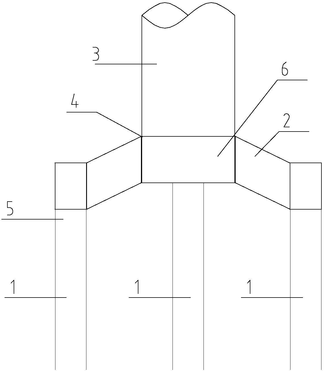
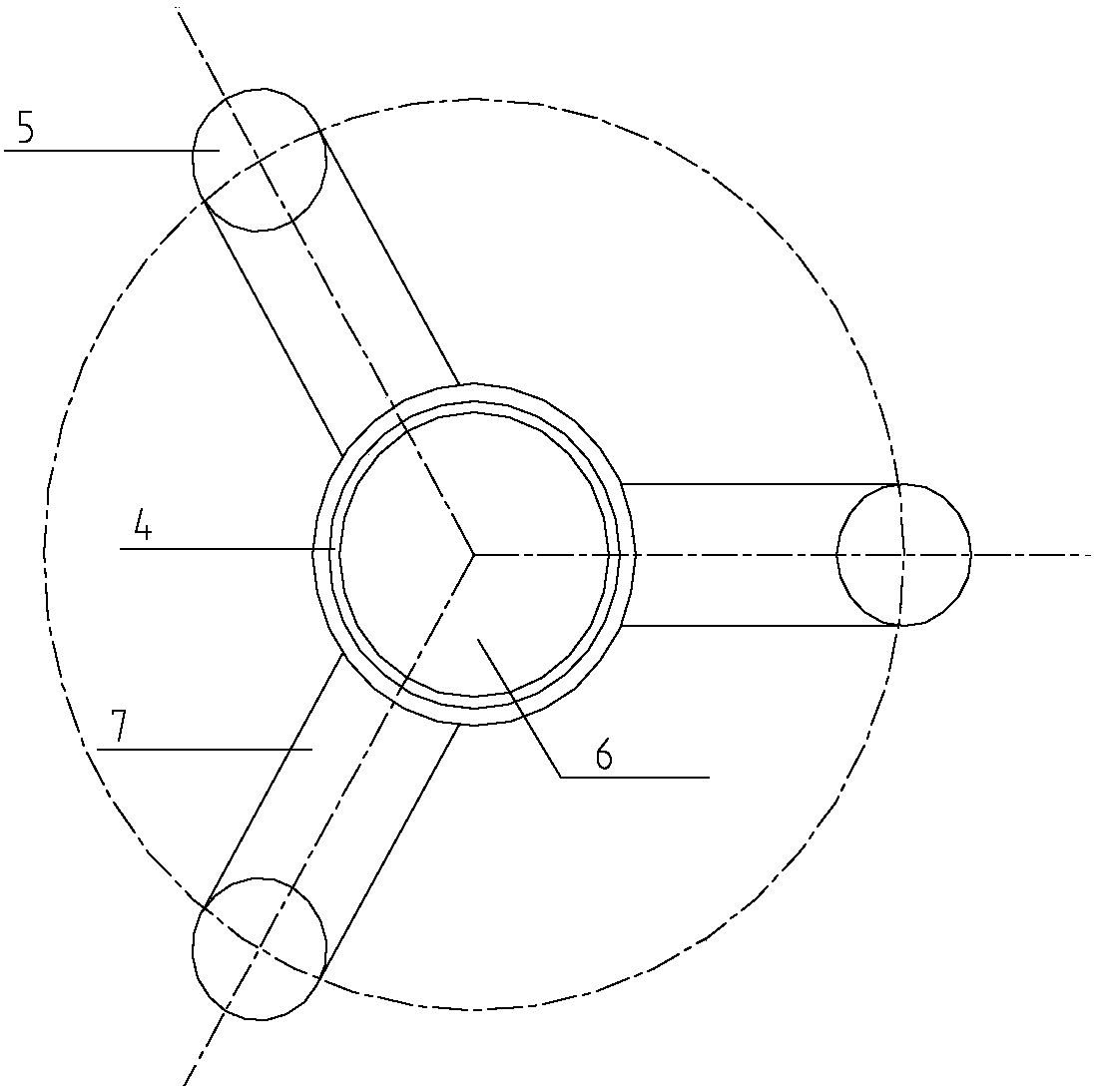
[0039] Such as figure 1 As shown, it is the foundation of the offshore wind power generating set of the present invention, which includes three steel pipe piles 1 and a steel cap 2 . The upper part of the steel cap 2 is provided with a flange 4 connected to the wind turbine tower 3. The steel cap has a central box 6 and several steel box girders 7 extending outward from the central box. The top of the central box 6 There is a flange 4 connected to the tower 3 of the wind power generating set, and vertical and horizontal reinforced steel ribs are arranged in the box.

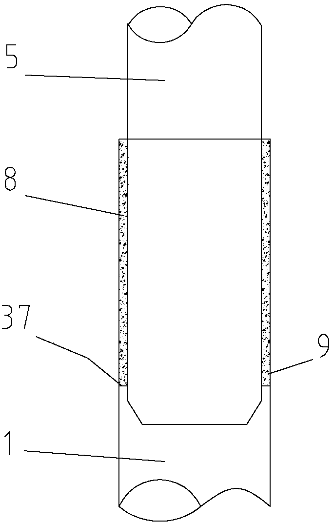
[0040] The end of each steel box girder away from the central box body is provided with steel cap pile legs 5, the number of steel cap pile legs matches the number of steel pipe piles and is socketed in the corresponding steel pipe piles.

[0041] Such as Figure 9 As shown, the steel pipe pile 1 is provided with a steel corbel 13 extending outward from the outer wall of the pile leg of the steel cap. When the...


PUM


Abstract

The invention discloses a pile cap foundation for an offshore wind turbine. The pile cap foundation comprises a steel pipe pile and a steel pile cap, wherein a steel pile cap pile leg is arranged at aposition, which is arranged at one end of a steel box girder, of the steel pile cap; the steel pile cap pile leg sleeves in the steel pipe pile; the steel pipe pile is used for positioning a driven pile by adopting a positioning formwork; the positioning formwork comprises a truss supporting pile, a positioning truss and a double-layer steel sleeve; the positioning truss and the truss supportingpile are connected together by virtue of the double-layer steel sleeve; a closure gap used for containing the steel pipe pile is formed in the center of an outer end of each branch part of the positioning truss; upper and lower layers of pile hoops are at least arranged at each closure gap; the steel pipe pile is fixedly held by the pile hoops; and a grouting material is filled into an annular clearance at the connecting part of the steel pipe pile and the steel pile cap pile leg, so that the steel pipe pile and the steel pile cap pile leg are connected to form a whole. The steel pipe pile andthe steel pile cap can be made in a steel structure processing plant in advance, only operations of piling, mounting and grouting need to be performed in the offshore construction site, and the offshore operation volume is greatly reduced.

Description

technical field [0001] The invention relates to the field of hydraulic structures, in particular to a pile cap foundation of an offshore wind power generating set. Background technique [0002] Pile foundations are an important structural type of offshore structures. At present, single pile foundations, jacket foundations, and high pile cap foundations are commonly used in offshore wind turbine foundations. [0003] Because the single pile foundation has only one pile foundation, it is a non-spatial structure with a small force arm. In order to meet the load from the wind turbine and various environmental loads, the pile diameter is required to be relatively large, and the pile diameter is basically greater than 7m. The equipment capacity requirements are high, and the construction is difficult. [0004] The basic structure of the jacket is complex, there are many rod nodes, and the process is cumbersome. The jacket is bulky and requires a large transport ship for transpor...

Claims


Application Information

Patent Timeline
Patent Type & Authority Applications(China)
IPC IPC(8): F03D13/25F03D13/10
CPCF03D13/10F03D13/25Y02E10/727Y02E10/72
Inventor 卢普伟程巧建吕黄陈楚生邹刚梁国栋张伟余青山
Owner CCCC FOURTH HARBOR ENG CO LTD
Why Eureka
Try Eureka