Laser radar on basis of optical fiber mode field adapter

A mode field adapter and lidar technology, applied in the directions of instruments, ICT adaptation, electromagnetic wave re-radiation, etc., can solve the problem that the laser beam is easily affected by vibration and changes in ambient temperature, humidity and pressure, the volume of the transmitting telescope telescope module increases, and the receiving The problem of reducing the effective receiving area of ​​the telescope, etc., can ensure the effective receiving area, expand the receiving field of view, and reduce the focal length.

Pending Publication Date: 2018-09-28
夏和娣
View PDF0 Cites 3 Cited by
  • Summary
  • Abstract
  • Description
  • Claims
  • Application Information

AI Technical Summary

Problems solved by technology

[0004] The inventors of the present invention found that increasing the focal length of the transmitting telescope will lead to an increase in the volume of the telescope module, and due to the increased focal length, the laser beam is more easily affected by vibration and changes in environmental temperature, humidity and pressure, thereby reducing the stability of the system
At the receiving telescope end, when the numerical aperture NA of the coupling fiber is constant, reducing the focal length of the telescope will reduce the effective receiving area of ​​the receiving telescope, thereby reducing the detection performance of the lidar; if a large mode field fiber coupling is used, Then the subsequent optical signal processing needs to use large mode field fiber, which greatly increases the difficulty of optical signal detection and processing. Some optical receivers cannot work with large mode field fiber. In addition, multimode photodetectors also have high cost and high performance. bad question
Therefore, large mode field fibers limit the application of some lidars, especially wind lidar, depolarization lidar and temperature lidar
These defects greatly limit the development of lidar

Method used


Image

  • Laser radar on basis of optical fiber mode field adapter
  • Laser radar on basis of optical fiber mode field adapter

Examples


Embodiment 1

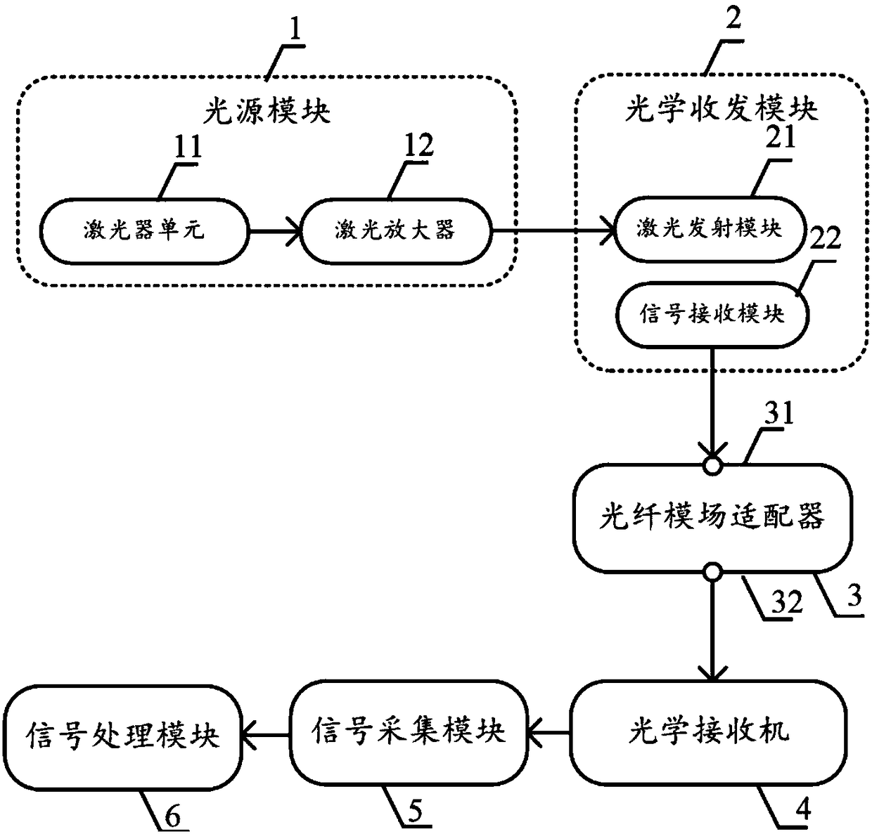
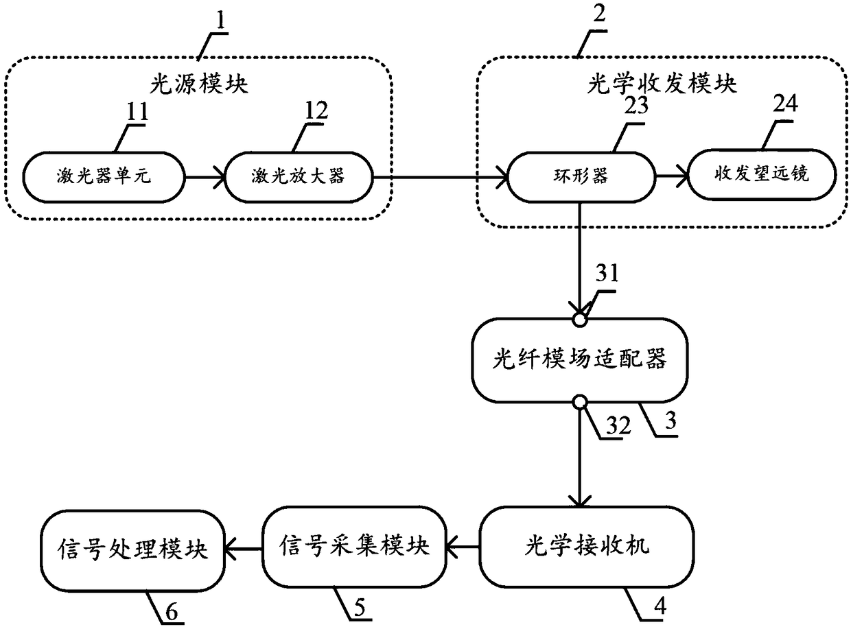
[0034] figure 1 It is a structural block diagram of a laser radar based on an optical fiber mode field adapter provided by an embodiment of the present invention, such as figure 1 Shown: including: light source module 1, optical transceiver module 2, optical fiber mode field adapter 3, optical receiver 4, signal acquisition module 5 and signal processing module 6; wherein:

[0035] The light source module 1 includes a laser unit 11 and a laser amplifier 12 , the laser unit 11 is used to output laser pulses; the laser amplifier 12 is used to amplify the laser pulses output by the laser unit 11 .

[0036]In one embodiment, the laser unit 11 includes a continuous light laser and a laser pulse generator; the output end of the continuous light laser is connected to the input end of the laser pulse generator, and the output end of the laser pulse generator is connected to the laser amplifier 12 The input end of the laser amplifier 12 is connected to the input end of the optical tra...


PUM


Abstract

The invention discloses laser radar on the basis of an optical fiber mode field adapter. The laser radar has the advantages that the optical fiber mode field adapter is used in a telescope of the laser radar, an input end of the optical fiber mode field adapter is a large-mode-field optical fiber end, the large-mode-field optical fiber end is connected with an output end of an optical receiving and transmitting module and is used for receiving atmospheric echo signals, an output end of the optical fiber mode field adapter is a small-mode-field optical fiber end, the small-mode-field optical fiber end is connected with an optical receiver and is favorable for optical filtering and optical signal extraction, and accordingly the cost of the laser radar can be reduced; the problem of contradiction between received signal view field angles and optical data processing of existing laser radar can be ingeniously solved by the aid of the optical fiber mode field adapter, view field angles can be expanded while the echo signal coupling efficiency is guaranteed, the performance of the laser radar can be improved, the requirements of the optical receiver and photoelectric detectors on small mode fields can be met, follow-up data processing difficulty can be lowered, the integral performance of the laser radar can be improved, and the application range of the laser radar can be expanded.

Description

technical field [0001] The invention relates to a laser radar, in particular to a laser radar based on an optical fiber mode field adapter. Background technique [0002] The basic principle of meteorological lidar is: the outgoing laser pulse interacts with the atmosphere, the atmospheric backscattering signal is collected by an optical antenna and then input to an optical receiver, and a series of key atmospheric parameters are obtained after photoelectric detection and data processing. Such as aerosol concentration, PM2.5 value, cloud height, temperature, humidity, visibility, atmospheric composition (such as water vapor, various polluting gases), etc. [0003] Lidar requires that the viewing angle of the receiving telescope is greater than the divergence angle of the emitting laser. The inventors of the present invention have found that in order to meet the above requirements when designing the laser radar, it is necessary to reduce the divergence angle of the emitted la...

Claims


Application Information

Patent Timeline
Patent Type & Authority Applications(China)
IPC IPC(8): G01S7/481G01S17/95
CPCG01S7/481G01S17/95Y02A90/10
Inventor 夏和娣张苏
Owner 夏和娣
Why Eureka
Try Eureka