Resistance brazing wire harness and processing technique thereof

A resistance brazing and wiring harness technology, applied in the direction of circuits, electrical components, conductive connections, etc., can solve problems such as temperature rise in the crimping area, intensified oxidation, and potential safety hazards for vehicles and passengers, achieving smooth and beautiful joints and small brazing deformation , Avoid the effect of electrical performance attenuation

Pending Publication Date: 2018-09-28
昆山徳可汽车配件有限公司
View PDF9 Cites 0 Cited by
  • Summary
  • Abstract
  • Description
  • Claims
  • Application Information

AI Technical Summary

Problems solved by technology

[0002] The traditional automotive wiring harness is connected to the terminal through the cold crimping process. There is only surface contact between the terminal and the wire, and there is a gap directly between the copper wire of the wire. The contact resistance of the connection position is greater than the resistance of the material itself. Moreover, during long-term use, the crimping area will slowly oxidize in the air, and the resistance will increase. In addition, the temperature of the crimping area will rise after the vehicle is powered on, which will aggravate the oxidation phenomenon and form a vicious circle. There is a long-term use of the wire harness. If the traditional crimped wiring harness is applied to the field of electric vehicle wrapped wiring harness, taking into account the high voltage and high current phenomenon between the battery modules, if the above-described problems occur, it may damage the vehicle and safety hazard for passengers

Method used


Image

  • Resistance brazing wire harness and processing technique thereof
  • Resistance brazing wire harness and processing technique thereof
  • Resistance brazing wire harness and processing technique thereof

Examples


Embodiment 1

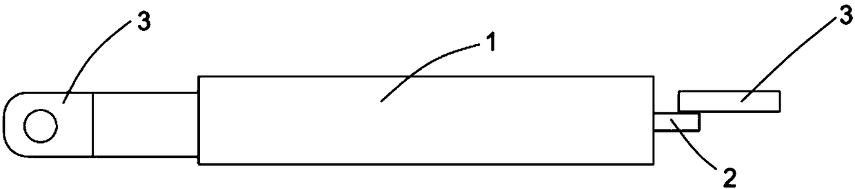
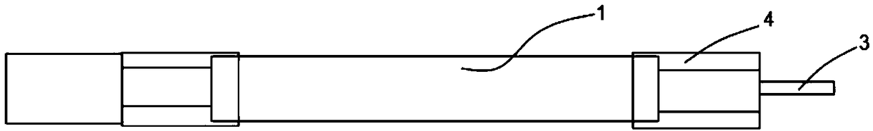
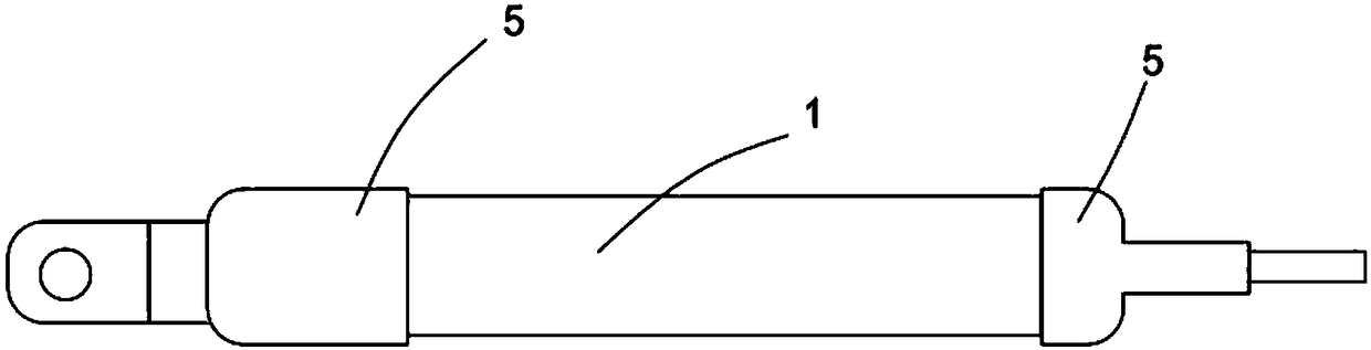
[0027] The present invention proposes a resistance brazing wire harness, which includes an aluminum wire 1, the end of the aluminum wire 1 is covered with an aluminum tube 4 and a copper plate 2 is welded by friction, and the copper plate 2 is provided with a special-shaped terminal 3. The copper plate 2 and the special-shaped terminal 3 are connected by solder, wherein the solder is a copper-silver alloy, and a heat-shrinkable tube 5 is provided outside the copper plate 2 and the special-shaped terminal 3 .

[0028] A resistance brazing wire harness processing technology, comprising the following steps:

[0029] S1: wire bonding, take a certain length of aluminum wire 1, open and strip the end of the processed aluminum wire 1, and insulate

[0030] The layer is peeled off, the aluminum wire 1 with the insulation layer peeled off is stretched into the aluminum tube 4, and put into a pressing mold for pressing to ensure that

[0031] The cross-section of the press fit is circu...

Embodiment 2

[0042] Take the aluminum wire, connect the copper terminal on the aluminum wire by cold pressing, and obtain the wire rod.


PUM


Abstract

The invention provides a resistance brazing wire harness and a processing technique thereof. The end of an aluminum wire is sleeved with an aluminum tube and welded with a copper plate by friction, aspecial-shaped terminal is arranged on the copper plate, and the copper plate is connected with the special-shaped terminal through a solder. The technique comprises: S1: wire pressing, S2: cutting the aluminum wire in a cutting machine to ensure that the end face is flat; S3: friction welding, S4: resistance brazing, wherein the brazing process adopts a metal material having a melting point lowerthan a base material as the solder, the base material is wetted by the liquid solder to fill the joint gap, and the solder is diffused with the base material to realize the connection of the terminaland the wire, so the brazing deformation is small, and the joint is smooth and attractive; molecular diffusion into a whole is realized in part of the welding zone of the copper wire and the terminalby resistance brazing, and the remaining part is completely filled by the solder, which ensures the seamless connection of the copper wire and the terminal, thereby avoiding electrical property attenuation caused by air oxidation in the connection zone.

Description

technical field [0001] The invention relates to the field of automotive battery wire harnesses, in particular to resistance brazing type wire harnesses and their processing technology. Background technique [0002] The traditional automotive wiring harness is connected to the terminal through the cold crimping process. There is only surface contact between the terminal and the wire, and there is a gap directly between the copper wire of the wire. The contact resistance of the connection position is greater than the resistance of the material itself. Moreover, during long-term use, the crimping area will slowly oxidize in the air, and the resistance will increase. In addition, the temperature of the crimping area will rise after the vehicle is powered on, which will further aggravate the oxidation phenomenon and form a vicious circle. There is a long-term use of the wire harness. If the traditional crimped wiring harness is applied to the field of electric vehicle wrapped wir...

Claims


Application Information

Patent Timeline
Patent Type & Authority Applications(China)
IPC IPC(8): H01R4/20H01R4/60H01R4/62H01R4/72H01R11/11H01R43/00H01R43/02H01R43/05
CPCH01R4/20H01R4/60H01R4/625H01R4/72H01R11/11H01R43/00H01R43/02H01R43/0214H01R43/05
Inventor 田敏王慰莉王存立陆开明
Owner 昆山徳可汽车配件有限公司
Why Eureka
Try Eureka