A simulation test device and method for research on tire-road friction process

A simulation test and tire technology, applied in the direction of automobile tire testing, using mechanical devices, measuring devices, etc., can solve the problems of low reliability, large energy consumption, and increased equipment power, so as to improve accuracy and reliability, improve Precise, easy-to-arrange effects

Active Publication Date: 2020-10-30
CHANGAN UNIV
View PDF2 Cites 0 Cited by
  • Summary
  • Abstract
  • Description
  • Claims
  • Application Information

AI Technical Summary

Problems solved by technology

[0004] Chinese Patent Publication No. CN 104101552A discloses "a device for accelerated wear on the road surface", which can be used to simulate and study the wear between the tire and the road surface. Spraying carborundum on the road speeds up the wear. The working conditions simulated by this method are quite different from the actual situation of the wheels on the actual road. The reliability of the conclusion is relatively low.
[0005] Chinese Patent Publication No. CN 101532934A discloses "A Method and Device for Accelerated Loading Test of Main Drive Wheel Type Pavement Material". Because the centrifugal force has a destructive effect on the test pavement material, the test cylinder cannot be rotated at high speed and can only be tested at low speed, so the conclusion obtained is relatively different from the actual situation.
In addition, the technical solution adopts the method of braking the test tire to perform the slip test, which has the following problems: (1) the friction plate of the brake will generate a lot of heat during the working process, and the test cannot be continued due to the temperature rise; (2) ) The braking process consumes a lot of energy, which increases the power of the equipment; (3) It is difficult to control the slip rate of the wheel during braking, which will lead to difficulties in data analysis
[0006] In summary, the simulation conclusions of the existing simulation test devices are generally quite different from the actual situation, cannot accurately reflect the actual situation, and cannot meet the needs of friction process research.

Method used


Image

  • A simulation test device and method for research on tire-road friction process
  • A simulation test device and method for research on tire-road friction process
  • A simulation test device and method for research on tire-road friction process

Examples


Embodiment 1

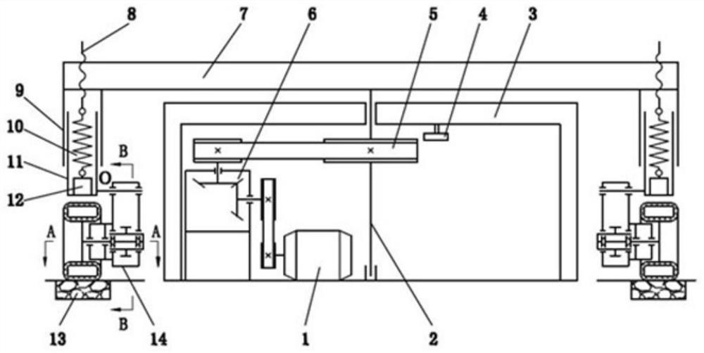
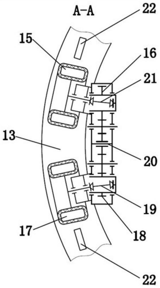
[0038] refer to Figure 1 to Figure 3 , a kind of simulation test device that is used for tire and road surface friction process research of the present invention comprises: driving device, transmission device, central shaft 2, rotating arm 7, loading device, transmission box 14, reference wheel 17, test wheel 15 and Test track 13. The transmission device is arranged between the driving device and the central shaft 2. The driving device can drive the central shaft 2 to rotate around its axis through the transmission device; The lower end of the central shaft 2 can be rotated on the base or foundation of the test device through bearings and other devices; both ends of the rotating arm 7 are connected with the transmission box 14 through the loading device, and the transmission box 14 can be applied perpendicular to the test by the loading device. The load of the track 13, when the rotating arm 7 rotates, the transmission box 14 can be driven by the loading device; the transmis...

Embodiment 2

[0053] refer to figure 1 , a kind of simulation test device that is used for tire and road surface friction process research of the present invention, motor 1 is connected with the input shaft of speed reducer 6 through transmission belt, and the output shaft of speed reducer 6 is connected with driven pulley 5 through belt, from The moving pulley 5 is fixed on the central shaft 2, the lower end of the central shaft 2 is supported on the ground by a bearing, the upper part of the central shaft 2 is supported on the support 3, and a rotating arm 7 is fixed on the top of the central shaft 2, and the two ends of the rotating arm 7 The end is provided with a first guide sleeve 9 and a screw 8, the screw 8 is located in the center of the guide sleeve, and a second guide sleeve 11 is arranged in cooperation with the inner wall of the first guide sleeve 9, and the second guide sleeve 11 is in the first guide The sleeve 9 can only move up and down and cannot rotate. A loading spring 1...

Embodiment 3

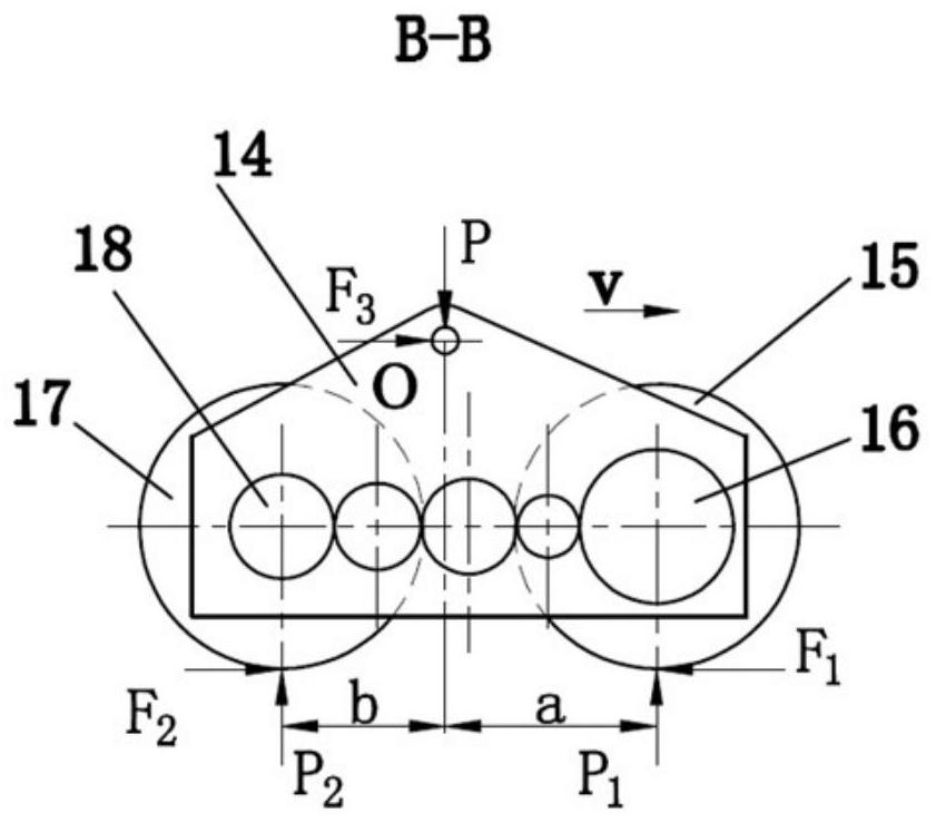
[0068] In this embodiment, the horizontal distance b from the axis of the reference gear 18 to the hinge point O is greater than the horizontal distance a from the axis of the test gear 16 to the hinge point O through structural adjustment, or the transmission box 14 acts on the two wheels through the counterweight adjustment. weight, so that P 2 1 ·z 2 / z 1 . Other structural parameters and test methods are the same as in Example 2.

[0069] At this time, the original reference wheel 17 produces a slipping motion and becomes a test wheel; the original test wheel 15 does not slip and becomes a reference wheel. The slipping process of the reference wheel 17 is similar to the slipping process of the driving wheel of the vehicle, and can be used to study the wear of the driving wheel of the vehicle.

[0070] At this time, the slip rate δ is calculated according to the following formula:

[0071] δ=1-z 2 / z 1 (4)

[0072] The coefficient of friction f between the referenc...


PUM


Abstract

The invention discloses a simulation test device and method for researching the friction process between tires and road surfaces, comprising: a transmission device is arranged between a driving device and a central shaft, and the driving device can drive the central shaft to rotate around the axis of the central shaft through the transmission device ; One end of the central shaft is fixedly provided with a rotating arm; the rotating arm is connected to the transmission box through a loading device; a rotatable reference gear and a test gear are arranged in the transmission box, and an intermediate gear is arranged between the reference gear and the test gear. Set in the transmission box, the reference gear is connected with the reference wheel through the reference universal joint, and the test gear is connected with the test wheel through the test universal joint; the test track is matched with the reference wheel and the test wheel. The simulation test device provided by the invention can accelerate the wear between the tire and the road surface, can more realistically simulate the slippage of the tire when running on the road surface, has no problem of brake heating, and has low energy consumption.

Description

technical field [0001] The invention belongs to the technical field of vehicle and road surface testing, in particular to a simulation test device and method for researching the friction process between tires and road surfaces. Background technique [0002] The effect of vehicle load on the road surface is mainly in the following ways: the vehicle load acting vertically on the road surface will cause permanent deformation and rutting on the road surface; The horizontal shear force will cause shear damage such as pushing on the road surface, and the surface of the road surface and tires will be gradually polished, resulting in the decline of the anti-skid performance of the tires when driving on the road surface, causing safety hazards. [0003] Research on the durability of pavement and tire surface function has become the necessity of developing new long-life pavement and tire. It has become an important issue in the transportation industry to simulate the sliding and grin...

Claims


Application Information

Patent Timeline
Patent Type & Authority Patents(China)
IPC IPC(8): G01N19/00G01M17/02
CPCG01M17/02G01N19/00
Inventor 韩森余丽洁韩霄彭标高巍洪宁郁录平
Owner CHANGAN UNIV
Why Eureka
Try Eureka