Air dehumidifier based on composite microporous membranes and dehumidifying equipment

A microporous membrane and dehumidifier technology, applied in the field of spacecraft environmental control, can solve the problems of multiple equipment and complex system structure

Inactive Publication Date: 2018-10-09
BEIJING INST OF SPACECRAFT ENVIRONMENT ENG
View PDF4 Cites 2 Cited by
  • Summary
  • Abstract
  • Description
  • Claims
  • Application Information

AI Technical Summary

Problems solved by technology

This method needs to provide cold source and heat source at the same time, the system structure is complicated, and there are many equipments

Method used


Image

  • Air dehumidifier based on composite microporous membranes and dehumidifying equipment
  • Air dehumidifier based on composite microporous membranes and dehumidifying equipment
  • Air dehumidifier based on composite microporous membranes and dehumidifying equipment

Examples


Embodiment Construction

[0022] The composite microporous membrane dehumidification method and device of the present invention will be described in detail below with reference to the accompanying drawings, but the description is only exemplary and not intended to limit the protection scope of the present invention.

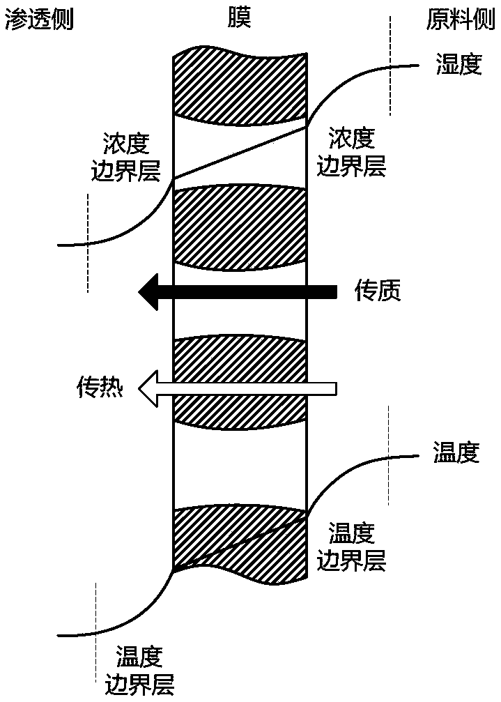
[0023] see figure 1 , figure 1 It shows a schematic diagram of water vapor passing through the hollow fiber membrane in the air dehumidification method of the composite microporous membrane of the present invention. The water vapor mass transfer process includes convective mass transfer on the wet air side, diffusion in the membrane, and convective mass transfer on the cold water side. Among them, the composite membrane separates the humid air from the low-temperature cold water, the low-temperature cold water flows through the permeation side of the composite membrane, the hot and humid air flows through the raw material side outside the membrane tube, and the water vapor condenses into ...


PUM


Abstract

The invention discloses an air dehumidifier based on composite microporous membranes. The air dehumidifier comprises end sockets, flanges, a longitudinally long middle tube shell structure, a pillar,connectors, cold water inlet and outlet flow passages, and air inlet and outlet flow passages. The two end sockets are used for fixing two ends of each membrane filament, and are respectively connected to the cold water inlet and outlet flow passages through the connectors and the flanges so that low-temperature cold water flows into the membrane filaments. The tube shell structure contains a plurality of clustered hollow fiber composite microporous membrane filaments, and is hermetically connected to the end sockets at two sides. The pillar disposed in the center axis of the tube shell structure is a supporting structure, ensuring that the membrane filaments have sufficient mechanical strength, and that the low-temperature cold water flows into the membrane filaments, exchanges heat withhigh-temperature high-humidity air fed and discharged from the air inlet and outlet flow passages arranged on the side surface of the tube shell structure, and then is conveyed into a sealing bin foruse. According to the air dehumidifier, temperature and humidity of wet air are reduced, and under combined functions of capillary force in micropores of the membranes and the water vapor partial pressure difference, transmission of water vapor to the cold water is achieved, and the water vapor valuable in a spacecraft cabin can be directly completely recovered.

Description

technical field [0001] The invention belongs to the field of spacecraft environment control, and specifically relates to an air dehumidification component and a corresponding system based on a composite microporous membrane of a spacecraft, which solves the problem of precise control of the humidity of the air in the spacecraft cabin, reduces power consumption of air dehumidification, and improves reliability. sex. Background technique [0002] Humidity control technology is an important aspect of manned spacecraft environmental control and life protection technology, and its basic task is to provide astronauts with a comfortable humidity environment. The relative humidity requirement for astronauts' comfortable environment is 28%-65%. When the relative humidity is lower than 25% or higher than 80%, the working time of astronauts in orbit cannot exceed 12 hours. In addition, due to the small space in the cabin of the manned spacecraft and the large number of electronic equi...

Claims


Application Information

Patent Timeline
Patent Type & Authority Applications(China)
IPC IPC(8): B01D53/26B01D63/00B64G1/50
CPCB01D53/26B01D63/00B64G1/50
Inventor 尚永红王晶陶东兴吕剑锋纪欣言侯雅琴袁卫星方以锦
Owner BEIJING INST OF SPACECRAFT ENVIRONMENT ENG
Why Eureka
Try Eureka