
Detection compensation control system for aerostatic spindle

An aerostatic spindle and compensation control technology, applied in manufacturing tools, measuring/indicating equipment, large fixed members, etc., to achieve detection compensation control, real-time compensation for rotor unbalanced displacement, and good dynamic response

Active Publication Date: 2018-10-09
BEIJING UNIV OF TECH
View PDF7 Cites 10 Cited by
  • Summary
  • Abstract
  • Description
  • Claims
  • Application Information

AI Technical Summary

Problems solved by technology

At present, the vibration control methods for the aerostatic spindle rotor mainly focus on the structural symmetry, cutting force load, thermal deformation and centrifugal force in the design stage, and there is no simple, effective, reasonable and complete aerostatic spindle rotor vibration detection and compensation control. system

Method used


Image

  • Detection compensation control system for aerostatic spindle
  • Detection compensation control system for aerostatic spindle
  • Detection compensation control system for aerostatic spindle

Examples


Embodiment Construction

[0019] The technical solution of the present invention will be described further below in conjunction with the accompanying drawings.

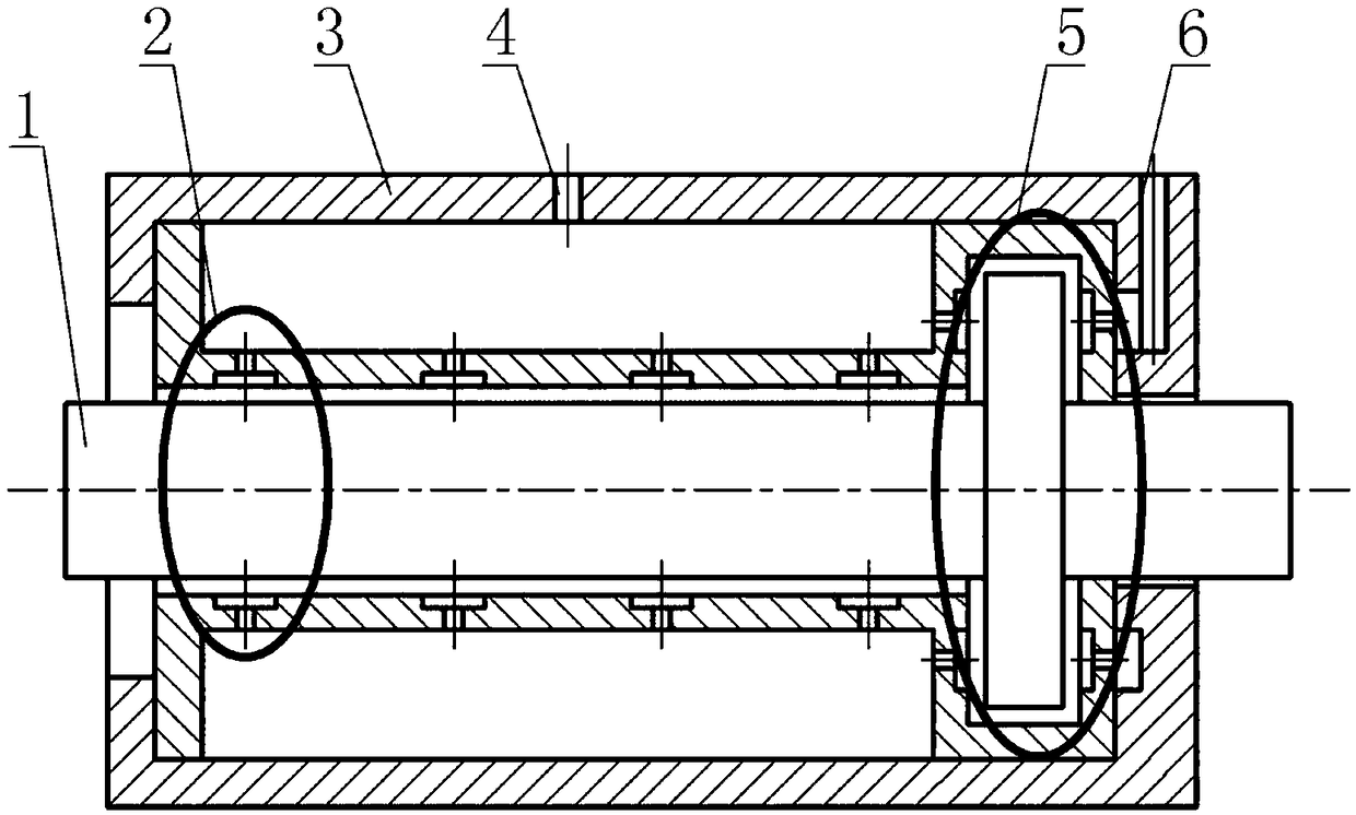
[0020] see figure 1 , the embodiment of the present invention is provided with an aerostatic spindle system. A detection compensation control system for an aerostatic spindle, the system includes a spindle rotor 1, a radial bearing 2, a bearing housing 3, a radial bearing air inlet 4, a thrust bearing 5, and a thrust bearing air inlet 6, The air enters the throttle hole and the air chamber through the radial bearing air inlet and the thrust bearing air inlet, forming a thin air film between the main shaft rotor 1 and the bearing sleeve, and the main shaft rotor 1 hardly generates friction.

[0021] This system includes a main shaft rotor 1, a radial bearing 2, a bearing housing 3, a radial bearing air inlet 4, a thrust bearing 5, and a thrust bearing air inlet 6. The main shaft rotor 1 is connected to and driven by a stepping motor, and has ...


PUM


Abstract

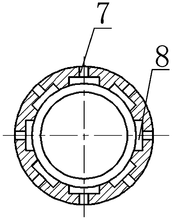
The invention discloses a detection compensation control system for an aerostatic spindle. The system comprises a spindle rotor, a radial bearing, a bearing shell, a radial bearing air inlet, a thrustbearing and a thrust bearing air inlet; air passes through the radial bearing air inlet and the thrust bearing air inlet to enter a throttling hole and an air cavity, a thin air film is formed between the spindle rotor and the bearing sleeve, and in the rotation process, the spindle rotor hardly generates friction. One aerostatic spindle system, four capacitor sensors, four piezoelectric actuators and a PC are arranged; the four capacitor sensors are fixed to the aerostatic bearing shell in an axis central symmetry manner, the four piezoelectric actuators are embedded in four elastic groovesof the aerostatic spindle in an axis central symmetry manner, and a capacitor sensor detection unit and a piezoelectric actuator unit are connected with the PC; vibration signals are received by the PC terminal, a piezoelectric controller is driven, and therefore real-time detection compensation control over the aerostatic spindle can be achieved.

Description

technical field [0001] The invention relates to a spindle vibration detection and compensation system, in particular to a detection, compensation and control system for the vibration of an aerostatic spindle rotor. Background technique [0002] In the aerostatic spindle system, the spindle rotor is an important component of the aerostatic spindle, and the operating state of the rotor determines the quality and accuracy of the processed workpiece to a great extent. In the process of workpiece processing, the vibration and rotation error of the spindle rotor are important indicators to measure the performance and machining accuracy of the spindle. The change of the vibration of the spindle rotor has a direct impact on the quality of the workpiece and the probability of defective products. Therefore, the rotor vibration is detected during the operation of the aerostatic spindle, and then the rotor offset is compensated, which corresponds to the improvement of the processing qua...

Claims


Application Information

Patent Timeline
Patent Type & Authority Applications(China)
IPC IPC(8): B23Q17/00B23B19/00
CPCB23Q1/70B23Q17/00
Inventor 陈东菊霍郴齐国超崔线线任佟王浩
Owner BEIJING UNIV OF TECH
Learn More