Movement planning method for mechanical arm

A technology of motion planning and robotic arm, applied in the field of robot control, can solve problems such as cumbersome process, achieve the effect of avoiding cumbersome process, improving control accuracy, and saving calculation amount

Inactive Publication Date: 2018-10-09
GUANGXI UNIVERSITY OF TECHNOLOGY
View PDF4 Cites 12 Cited by
  • Summary
  • Abstract
  • Description
  • Claims
  • Application Information

AI Technical Summary

Problems solved by technology

[0003] In the past, when there was a deviation in the initial position of the end of the redundant robotic arm, it was necessary to convert th

Method used


Image

  • Movement planning method for mechanical arm
  • Movement planning method for mechanical arm
  • Movement planning method for mechanical arm

Examples


Embodiment 1

[0047] Taking four degrees of freedom as an example, the construction process of the forward kinematics equation is as follows:

[0048] 1. In order to simplify the structure of the manipulator, the D-H parameters of the four-degree-of-freedom manipulator are set as follows:

[0049] D-H parameters of a four-degree-of-freedom manipulator

[0050] Connecting rod i

joint angle θ i

Torsion angle α i

Connecting rod length a i

Connecting rod offset d i

1

θ 1

0

l 1

0

2

θ 2

0

l 2

0

3

θ 3

0

l 3

0

4

θ 4

0

l 4

0

[0051] 2. Obtain the connecting rod transformation matrix of the manipulator through the D-H parameters:

[0052]

[0053]

[0054] where cθ 1 means cos(θ 1 ), sθ i Indicates that sin(θ i ), cθ 12 means cos(θ 1 +θ 2 ), sθ 1234 Indicates that sin(θ 1 +θ 2 ).

[0055] 3. The actual joint angle is set to θ=[0,π / 2,π / 4,0] T , the connectin...

Embodiment 2

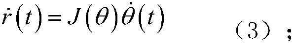
[0060] Also taking the 4-DOF robotic arm as an example, the Jacobian matrix is ​​constructed as follows:

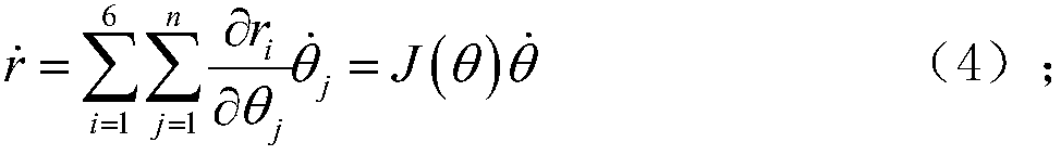
[0061] For a mechanical arm with a series structure with n degrees of freedom, the relationship between the Cartesian space motion velocity vector and the joint coordinate vector is:

[0062]

[0063] where i=1,2,...6 represent the number of translational linear velocity vectors and rotational angular velocity vectors of the end effector of the manipulator along the X, Y and Z directions respectively, and j=1,2,...n represent the number of joints of the manipulator number.

[0064] The 6×n Jacobian matrix is ​​as follows:

[0065]

[0066] Since the four-degree-of-freedom robotic arm in this patent has 4 joints, and the robotic arm works in a two-dimensional plane, the specific Jacobian matrix involved is:

[0067]

[0068] where cθ 1 means cos(θ 1 ), sθ i Indicates that sin(θ i ), cθ 12 means cos(θ 1 +θ 2 ), sθ 1234 Indicates that sin(θ 1 +θ 2 ).

Embodiment 3

[0070] Taking the 4-DOF mechanical arm as an example, the whole process of the present invention is as follows:

[0071] The desired initial position joint angle of the robotic arm is set to [π / 6,π / 12,π / 6,0] T , the actual position of the robot arm is set to [0,π / 2,π / 4,0] T , the length of the four connecting rods is set to l=[1,0.8,0.7,0.5] T . Set the length of the four connecting rods of the robotic arm as l=[1,0.8,0.7,0.5] T , the task period T is 10s, λ 0 set to 5;

[0072] Parameter configuration when setting position deviation λ(t)=λ 0 [1-cos(2πt / T)],λ 0 is a scalar coefficient that can be set arbitrarily, and T represents the cycle of the manipulator to perform tasks;

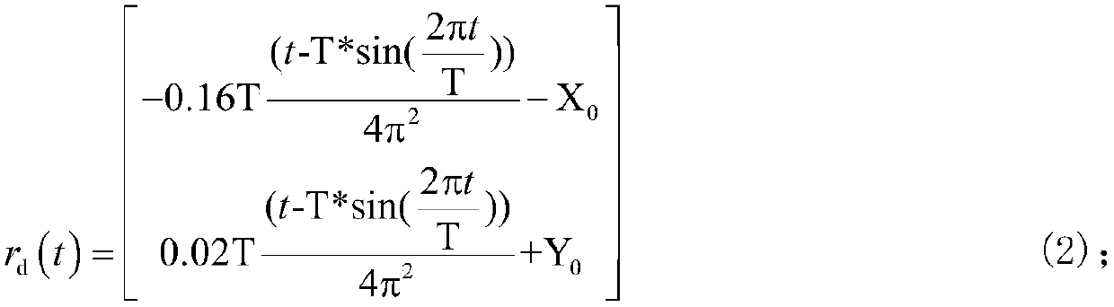
[0073] First, set the desired joint angle θ of the manipulator d (0) and the actual joint angle θ(0) are respectively substituted into the following forward kinematics equation (1) for forward kinematics analysis of the manipulator:

[0074] r(t)=f(θ(t)) (1);

[0075] The expected initial posi...


PUM


Abstract

The invention discloses a movement planning method for a mechanical arm. The method comprises the following steps: A, measuring the actual position of the tail end of the mechanical arm and the expected initial position of the tail end of the mechanical arm when the mechanical arm is in an initial state, and calculating the position error of the tail end of the mechanical arm; and B, constructinga Cartesian velocity equation of the mechanical arm, and solving the joint velocity of the mechanical arm by means of pseudo-inverse Jacobian matrix combined with the Cartesian velocity equation of the mechanical arm. The method disclosed by the invention can save the calculated amount greatly, is accurate in calculating result, and can improve the executing precision of the mechanical arm effectively.

Description

technical field [0001] The invention belongs to the technical field of robot control, and specifically relates to a method for planning motion of a robot arm. Background technique [0002] The redundant manipulator is a terminal active mechanical device with a degree of freedom greater than the minimum degree of freedom required by the task space. Its motion tasks include welding, painting, assembly, excavation, and drawing, etc. It is widely used in equipment manufacturing, product processing, and machine operations. and other national economic production activities. The inverse kinematics problem of the redundant manipulator refers to the problem of determining the joint angle of the manipulator given the end pose of the manipulator. When there is a deviation between the initial position of the end of the redundant manipulator and the initial position of the expected trajectory, the deviation always exists during the execution of the specified trajectory tracking task, re...

Claims


Application Information

Patent Timeline
IPC IPC(8): B25J9/16
CPCB25J9/1664
Inventor 李克讷杨津徐剑琴齐杨
Owner GUANGXI UNIVERSITY OF TECHNOLOGY
Why Eureka
Try Eureka