Deflagration-to-detonation transition energy gathering explosive device
A combustion-to-detonation and energy-gathering technology, which is applied in the field of energy-gathering explosive devices and combustion-to-detonation energy-gathering explosive devices, can solve problems such as unstable spark ignition, inability to generate energy-gathering jets, and incomplete detonation , to achieve the effects of improving heat release capability, ignition reliability and complete detonation
- Summary
- Abstract
- Description
- Claims
- Application Information
AI Technical Summary
Problems solved by technology
Method used
Image
Examples
Embodiment 1
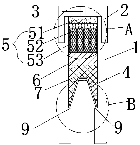
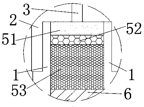
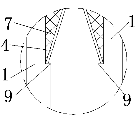
[0035] Example 1. like Figure 1-5 As shown, a combustion-to-detonation concentrated-energy explosive device includes a high-voltage electric spark ignition device and a concentrated-energy explosive device.
[0036] The energy-gathering explosive device comprises a charge container and a drug-type cover 4, and the charge container includes a cylindrical charge container body 1 and a top cover 2 installed on the top opening of the charge container body 1; There is an ignition electrode installation hole 3; a medicine-shaped cover 4 is installed in the powder-charging container body 1, and the top surface and the bottom surface of the medicine-shaped cover 4 are both small up and down big cones or the top and bottom surfaces of the medicine-shaped cover 4 are both upper and lower. Small and large conical frustum; the top of the drug type cover 4 in the charge container body 1 is sequentially equipped with a primary explosive layer 5, a booster explosive layer 6, and a high explo...
Embodiment 2
[0059] Example 2. like Figure 6-7 As shown, the difference between this embodiment and Embodiment 1 is that the mixed charge layer 51 is divided into the upper layer 54 of the mixed charge layer and the lower layer 55 of the mixed charge layer from top to bottom, and the density range of the upper layer 54 of the mixed charge layer 0.5~0.7g / cm 3 , the density range of the lower layer 55 of the mixed charge layer is 0.7~0.9g / cm 3 The bottom opening of the ignition electrode installation hole 3 on the top surface of the mixed charge layer upper layer 54 is provided with a recess 56 with an upward opening, and the two ignition electrodes 82 are located in the recess 56; the mixed charge layer upper layer 54, the mixed charge layer The volume ratio of the lower layer 55, the bulk RDX layer 52, and the RDX column 53 is 2:2:3.5:6; the density of the RDX column 53 is 1.3g / cm 3 . The mixed charge layer 51 is a mixture of black powder, active metal powder, perchlorate and nitrocel...
Embodiment 3
[0065]Example 3. The difference between this embodiment and Embodiment 1 is that the mixed charge layer 51 includes a circular cylindrical outer layer 57 of the mixed charge layer and a cylindrical mixed charge embedded in the outer layer 57 of the mixed charge layer. The inner layer 58 of the drug layer and the outer layer 57 of the mixed charge layer have a density ranging from 0.7 to 0.9 g / cm 3 , the density range of the inner layer 58 of the mixed charge layer is 0.5~0.7g / cm 3 The central axis of ignition electrode installation hole 3, the central axis of mixed charge layer outer layer 57, the central axis of mixed charge layer inner layer 58 and the central axis of charge container body 1 are on the same straight line; The bottom opening of the ignition electrode installation hole 3 on the top surface of the layer 58 is provided with a pit 59 with an upward opening, and the two ignition electrodes 82 are located in the pit 59; The volume ratio is 2.5:2.5:6; the density ...
PUM
| Property | Measurement | Unit |
|---|---|---|
| Density | aaaaa | aaaaa |
| Density | aaaaa | aaaaa |
| Density | aaaaa | aaaaa |
Abstract
Description
Claims
Application Information
 - R&D
- Intellectual Property
- Life Sciences
- Materials
- Tech Scout
- Unparalleled Data Quality
- Higher Quality Content
- 60% Fewer Hallucinations
Browse by: Latest US Patents, China's latest patents, Technical Efficacy Thesaurus, Application Domain, Technology Topic, Popular Technical Reports.
© 2025 PatSnap. All rights reserved.Legal|Privacy policy|Modern Slavery Act Transparency Statement|Sitemap|About US| Contact US: help@patsnap.com


