Microwave same-frequency signal interference suppression and down-conversion receiving device and method

A technology for interference suppression and co-frequency signals, which is applied in the phase modulation carrier system, electromagnetic wave transmission system, distortion/dispersion elimination, etc., can solve the problems of periodic fading of useful signals, affecting the suppression level of interference signals, etc., and achieve the effect of periodic fading The effect of reducing, realizing optical down-conversion, and simple structure

Active Publication Date: 2018-10-09
EAST CHINA NORMAL UNIV
View PDF5 Cites 14 Cited by
  • Summary
  • Abstract
  • Description
  • Claims
  • Application Information

AI Technical Summary

Problems solved by technology

[0005] Aiming at the deficiencies of the prior art, the present invention proposes a microwave co-frequency signal interference suppression and down-conversion receiving device and method, which uses a single optical modulator structure, and simultaneously realizes the suppression of co-frequency interference signals in the optical domain and the detection of useful signals Down-conversion, while solving the two problems in the prior art that the fiber dispersion affects the interference signal suppression level and introduces periodic fading to the useful signal

Method used


Image

  • Microwave same-frequency signal interference suppression and down-conversion receiving device and method
  • Microwave same-frequency signal interference suppression and down-conversion receiving device and method
  • Microwave same-frequency signal interference suppression and down-conversion receiving device and method

Examples


Embodiment 1

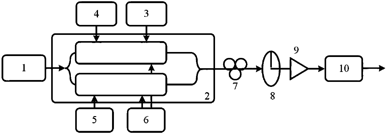
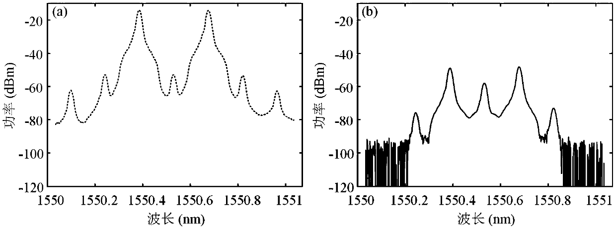
[0057] In this embodiment, the wavelength of the optical signal output by the laser is 1550.55 nm. Adjust the DC bias voltage so that the two sub-MZMs of the sub-DP-MZM that input the receiving signal and interference signal at the RF input port are biased at the minimum transmission point, and the main MZM is biased at the minimum transmission point; make the RF input port input the local oscillator signal The two sub-MZMs of the sub-DP-MZM are biased at the minimum transmission point, and the main MZM is biased at the maximum transmission point. In this embodiment, the suppression performance of single-frequency and co-channel interference signals is mainly studied. At this time, the useful signal in the received signal is set to 0, that is, the received signal only contains the interference signal. figure 2 When the frequency of the input signal is 18 GHz, the spectrogram (a) of the output optical signal of the sub-DP-MZM of the input receiving signal and interference sign...

Embodiment 2

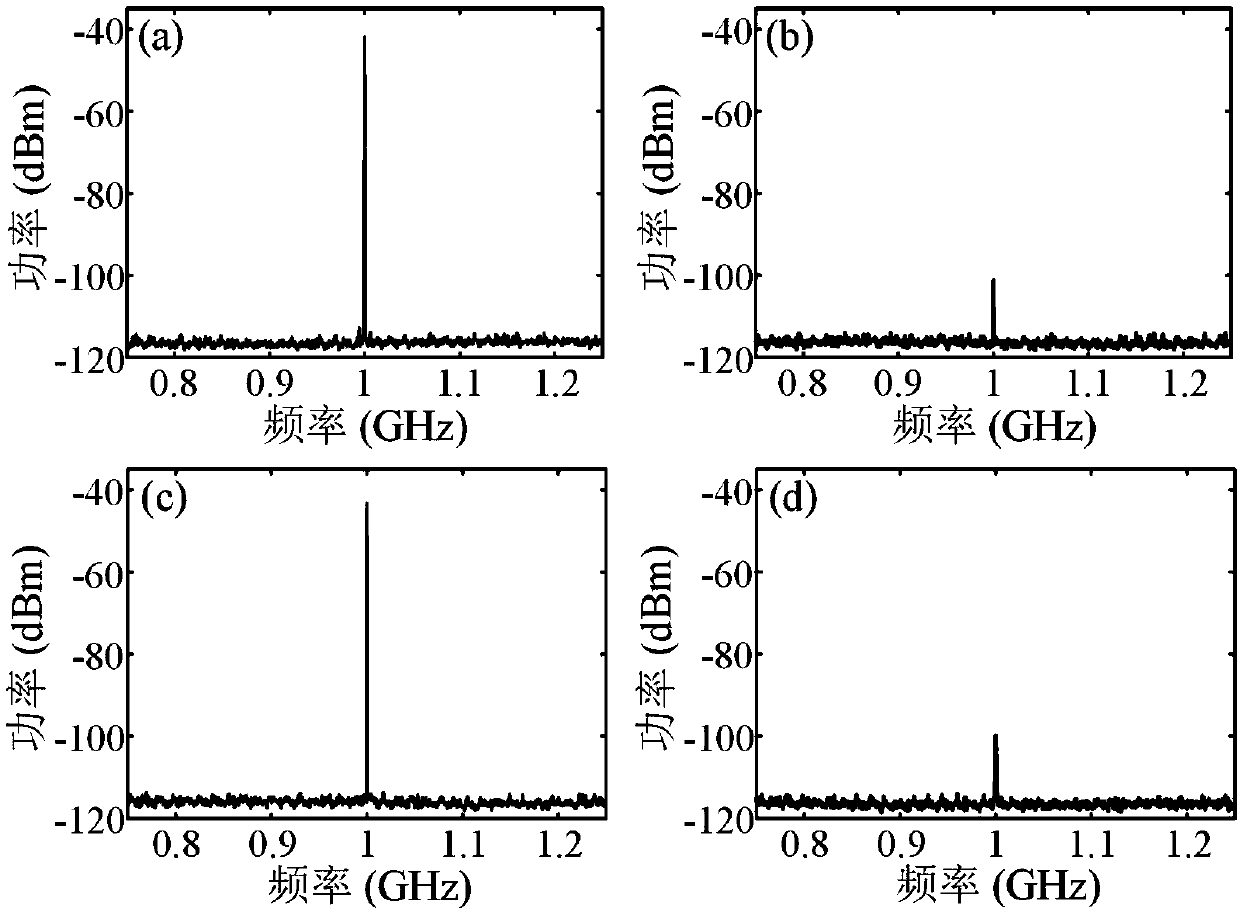
[0059] In this embodiment, the wavelength of the optical signal output by the laser is 1550.55 nm. Adjust the DC bias voltage so that the two sub-MZMs of the sub-DP-MZM that input the receiving signal and interference signal at the RF input port are biased at the minimum transmission point, and the main MZM is biased at the minimum transmission point; make the RF input port input the local oscillator signal The two sub-MZMs of the sub-DP-MZM are biased at the minimum transmission point, and the main MZM is biased at the maximum transmission point. In this embodiment, the suppression performance of broadband co-frequency interference signal is mainly studied. At this time, the interference signal in the received signal is set as a broadband QPSK modulation signal with a symbol rate of 200 Mbps, and the useful signal is a pure microwave signal of the same frequency. Figure 4 IF signal spectrogram generated for broadband co-channel interference suppression, Figure 4 (a)(b) are...


PUM


Abstract

The invention relates to a microwave same-frequency signal interference suppression and down-conversion receiving device and method, and belongs to the technical field of microwave signal processing.The microwave same-frequency signal interference suppression and down-conversion receiving device comprises a laser, polarization multiplexing DP-MZMs (dual-parallel Mach-Zehnder modulators) , a received signal simulator, an interference signal simulator, a local oscillator signal generator, a DC power supply, a polarization controller, a polarizer, an optical amplifier and a photoelectric detector, wherein the DP-MZMs are DP-QPSK (dual-polarization quadrature phase shift keying) modulators, one DP-MZM of the DP-QPSK modulators is used for suppressing an interference signal in received signalsin an optical domain and coupled with a local oscillator light signal generated by the other DP-MZM of the DP-QPSK modulators, and photovoltaic conversion is conducted at the photoelectric detector so that optical down conversion of the received signals is achieved. Same-frequency interference suppression and optical down-conversion of the received signals can be achieved simultaneously, and influence of optical fiber dispersion on same-frequency interference suppression level and power of the received signals in the signal optical fiber transmission process is reduced.

Description

technical field [0001] The invention relates to a microwave same-frequency signal interference suppression and down-conversion receiving device, which belongs to the technical field of microwave signal processing. Background technique [0002] In a traditional wireless communication system over optical fiber, the wireless uplink and the wireless downlink use different signal frequencies, and through frequency isolation, the uplink and downlink do not interfere with each other. With the popularization of voice, picture, high-definition video and other services in wireless communication systems and the demand for ultra-high-definition video services in the future, people's requirements for communication rates are getting higher and higher; on the other hand, wireless spectrum resources are limited. With the growth of people's wireless services, wireless spectrum resources are in short supply. In order to solve this problem, people have proposed the concept of the same-frequen...

Claims


Application Information

Patent Timeline
Patent Type & Authority Applications(China)
IPC IPC(8): H04B10/2513H04B10/556H04L27/20
CPCH04B10/2513H04B10/5561H04L27/20
Inventor 陈阳
Owner EAST CHINA NORMAL UNIV
Why Eureka
Try Eureka