RC-IGBT device and preparation method thereof

A technology of devices and drift regions, which is applied in semiconductor/solid-state device manufacturing, semiconductor devices, electrical components, etc., and can solve problems such as reliability, performance and hazards of devices in negative resistance regions

Active Publication Date: 2018-10-12
INST OF MICROELECTRONICS CHINESE ACAD OF SCI
View PDF10 Cites 5 Cited by
  • Summary
  • Abstract
  • Description
  • Claims
  • Application Information

AI Technical Summary

Problems solved by technology

[0005] The main purpose of the present invention is to provide a kind of RC-IGBT device and its preparation method, to solve the problem that the RC-IGBT in the prior art will produce a

Method used


Image

  • RC-IGBT device and preparation method thereof
  • RC-IGBT device and preparation method thereof
  • RC-IGBT device and preparation method thereof

Examples


preparation example Construction

[0046]According to another aspect of the present invention, there is also provided a method for preparing an RC-IGBT device, comprising the following steps: forming a first substrate having a drift region 7 and a field stop region 8, the field stop region 8 being located on one side of the drift region 7 Both the drift region 7 and the field stop region 8 have the first conductivity type; the first collector region 10 and the second collector region 9 are formed on the side of the first substrate close to the field stop region 8, and the first collector region 10 It has a first end, and the first end runs through the field stop region 8 to isolate the field stop region 8 into a first stop region and a second stop region, and the part of the first collector region 10 other than the first end Set in contact with the first cut-off region, the second collector region 9 is arranged in contact with the second cut-off region, the second collector region 9 has the first conductivity ty...

Embodiment 1

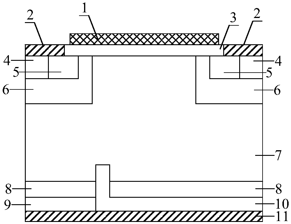
[0056] The RC-IGBT device provided by this embodiment is as image 3 As shown, its cells include gate 1, source 2, gate oxide layer 3, silicon carbide P + The contact area 4, silicon carbide N + The source region 5, silicon carbide P + The base region 6, silicon carbide N + The drift region 7, silicon carbide N + The field stop region 8, silicon carbide N + The second collector region 9, silicon carbide P + The first collector region 10 and the collector electrode 11 , the first collector region 10 has a first end portion, and the first end portion penetrates the field stop region 8 .


PUM


Abstract

The invention provides an RC-IGBT device and a preparation method thereof. The RC-IGBT device includes a first collector region with a first conductivity type and a second collector region with a second conductivity type; the first collector region has a first end portion extending through the field cut-off region for isolating a field cut-off region into a first cut-off region and a second cut-off region; the portion of the first collector region, other than the first end portion, is disposed in contact with the first cut-off region; and the second collector region is disposed in contact withthe second cut-off region. Due to the isolation of the first end portion of the first collector region to the field cut-off region, electrons or holes need to climb over the first end portion, whichincreases carrier motion path, thereby increasing the potential difference of the RC-IGBT device, above the first collector region, in the initial period of conduction, making the PN junction easier to turn on, the device easier to switch from unipolar conduction to bipolar conduction, further suppressing the Snapback effect of the RC-IGBT device in the initial conduction period.

Description

technical field [0001] The invention relates to the technical field of semiconductors, in particular to an RC-IGBT device and a preparation method thereof. Background technique [0002] Silicon carbide (SiC), as a wide band gap semiconductor material that has attracted much attention in recent years, has good physical and electrical properties such as wide band gap, high critical breakdown electric field, high thermal conductivity, and high electron saturation drift velocity. Therefore, it has broad application prospects in many fields such as high temperature, high pressure, high frequency, high power, and radiation resistance, and meets the requirements of the next generation of power electronic equipment for power devices with higher power, smaller size and harsher conditions. Gradually applied to various power electronic system fields. [0003] Insulated gate bipolar transistor (IGBT) is a composite fully-controlled voltage-driven power semiconductor device composed of ...

Claims


Application Information

Patent Timeline
IPC IPC(8): H01L29/739H01L29/08H01L21/04
CPCH01L29/0821H01L29/66068H01L29/7395
Inventor 谭犇田晓丽白云宋瓘顾航杨成樾汤益丹陈宏刘新宇
Owner INST OF MICROELECTRONICS CHINESE ACAD OF SCI
Why Eureka
Try Eureka