Darlington distributed power amplifier based on linearization stacking technology

A power amplifier and linearization technology, applied in power amplifiers, amplifiers, amplifiers with semiconductor devices/discharge tubes, etc., can solve the problem of limited ultra-broadband high-power amplification capability, reduced output power characteristics, high-power and high-efficiency amplification Capability limitation and other issues, to achieve good broadband power output capability and power gain capability, improve stability and reliability, and avoid the effect of low breakdown voltage characteristics

Pending Publication Date: 2018-10-12
QINGHAI UNIV FOR NATITIES +2
View PDF0 Cites 2 Cited by
  • Summary
  • Abstract
  • Description
  • Claims
  • Application Information

AI Technical Summary

Problems solved by technology

[0004] (1) High-power high-efficiency amplification capability is limited: the characteristic frequency of transistors in semiconductor processes is getting higher and higher, which leads to low breakdown voltage and limits the power capacity of a single transistor
In order to obtain high power capability, multi-channel transistor power synthesis is often required, but the efficiency of the power amplifier is relatively low due to the energy loss of the multi-channel synthesis network, so the high power and high efficiency capabilities are poor
[0005] (2) Ultra-broadband high power amplification capability is limited: in order to meet the high power index, multiple transistor power synthesis is required, but the load impedance of multi-channel synthesis is greatly reduced, resulting in a very high impedance conversion ratio; in high impedance conversion ratio Realizing broadband characteristics is a great challenge
[0007] ① In the traditional distributed power amplifier, the core amplifier circuit is realized by multiple single transistors in a distributed amplification arrangement. Since the single transistor is affected by para...

Method used


Image

  • Darlington distributed power amplifier based on linearization stacking technology
  • Darlington distributed power amplifier based on linearization stacking technology
  • Darlington distributed power amplifier based on linearization stacking technology

Examples


Embodiment Construction

[0023] Exemplary embodiments of the present invention will now be described in detail with reference to the accompanying drawings. It should be understood that the implementations shown and described in the drawings are only exemplary, intended to explain the principle and spirit of the present invention, rather than limit the scope of the present invention.

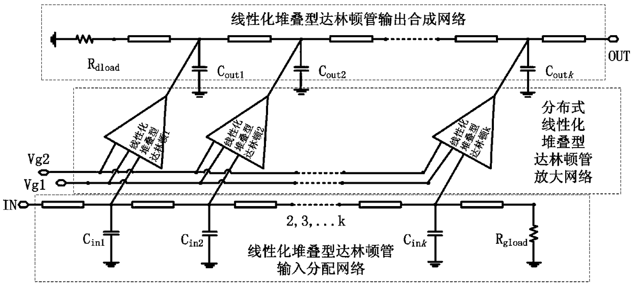
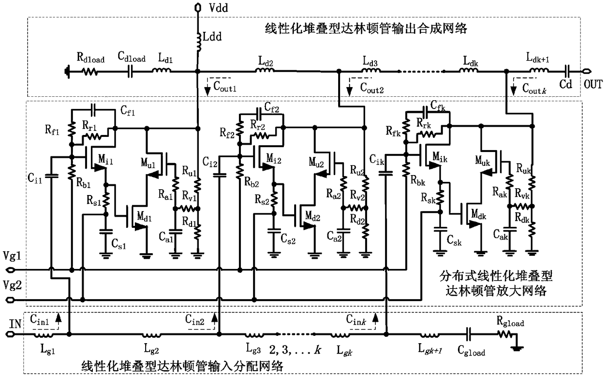
[0024] The embodiment of the present invention provides a Darlington distributed power amplifier based on linearized stacking technology, such as figure 1 As shown, including distributed linearized stacked Darlington tube amplification network, linearized stacked Darlington tube input distribution network, linearized stacked Darlington tube output synthesis network, distributed linearized stacked Darlington tube output synthesis network, distributed linearized stacked Darlington tube The tube amplification network consists of k linearized stacked Darlington tubes, where k is greater than or equal to 3; the input end of the...


PUM


Abstract

The invention discloses a Darlington distributed power amplifier based on a linearization stacking technology, comprising a distributed linearization stacked Darlington transistor amplification network, a linearization stacked Darlington transistor input distribution network and a linearization stacked Darlington transistor output synthesis network. A core architecture of the invention adopts thedistributed linearization stacked Darlington transistor amplification network, and the amplification network is composed of three distributed Darlington transistors based on the linearization stackingtechnology at least; meanwhile, the invention considers influence of a two-transistor linearization stacked Darlington transistor on equivalent capacitance of an input and output artificial transmission line, accuracy of circuit design is greatly improved, and difficulty of circuit debugging in later period is reduced, so that the whole power amplifier obtains good broadband power output capability and power gain capability, and stability and reliability of a circuit are improved.

Description

technical field [0001] The invention relates to the fields of heterojunction bipolar transistor radio frequency power amplifiers and integrated circuits, in particular to a high-efficiency, high-output-power, high-gain distributed power amplifier applied to a transmitting module at the end of an ultra-wideband transceiver. Background technique [0002] With the rapid development of electronic warfare, software radio, ultra-wideband communication, wireless local area network (WLAN) and other military electronic warfare and communication, and civilian communication markets, RF front-end transceivers are also developing in the direction of high performance, high integration, and low power consumption. Therefore, the market urgently needs the radio frequency and microwave power amplifier of the transmitter to have ultra-wideband, high output power, high efficiency, low cost and other performances, and the integrated circuit is the key technology that is expected to meet the marke...

Claims


Application Information

Patent Timeline
IPC IPC(8): H03F3/24H03F3/193
CPCH03F3/193H03F3/245
Inventor 邬海峰刘林盛林倩朱琳张晓明周杨严杰
Owner QINGHAI UNIV FOR NATITIES
Why Eureka
Try Eureka