
Equipment for recovering cooling liquid for machining tool

A technology for processing machine tools and recycling equipment, which is applied to metal processing equipment, metal processing machinery parts, filter circuits, etc. It can solve problems such as the inability to remove solid particulate matter and dust, reduce the service life of the filter, and fail to achieve the filtering effect. The effect of reducing working pressure, improving filtration strength and improving efficiency

Inactive Publication Date: 2018-10-16
芜湖中驰机床制造有限公司
View PDF7 Cites 8 Cited by
  • Summary
  • Abstract
  • Description
  • Claims
  • Application Information

AI Technical Summary

Problems solved by technology

[0004] At present, filter screens are used in filtering equipment, and in general equipment, the recovered coolant directly impacts the filter screen, which not only makes the filtering effect poor, but also reduces the service life of the filter screen; at the same time, the filter screen cannot remove some solids. Particulate matter and dust, so the desired filtering effect cannot be achieved

Method used


Image

  • Equipment for recovering cooling liquid for machining tool
  • Equipment for recovering cooling liquid for machining tool
  • Equipment for recovering cooling liquid for machining tool

Examples


Embodiment Construction

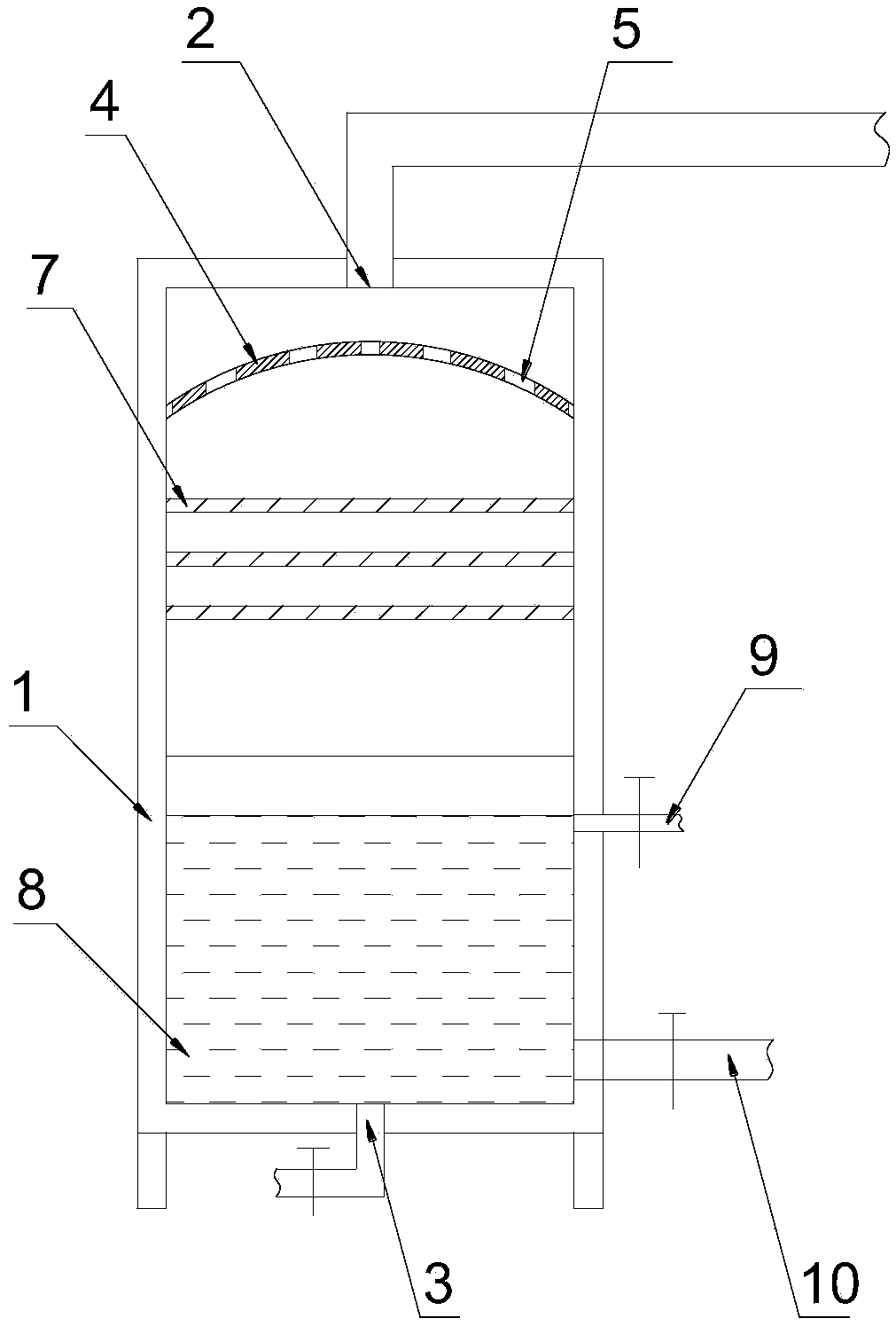
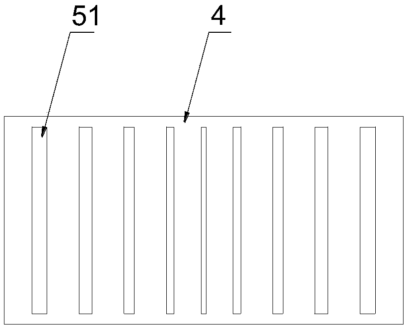
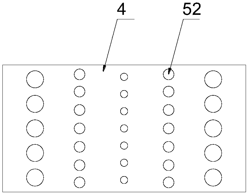
[0022] Such as Figure 1-3 as shown, figure 1 It is a structural schematic diagram of the cooling liquid recovery equipment for processing machine tools proposed by the present invention; figure 2 It is a top view of the splitter plate in the coolant recovery equipment for processing machine tools proposed by the present invention; image 3 It is a schematic diagram of other embodiments of the splitter plate in the cooling liquid recovery equipment for processing machine tools proposed by the present invention.

[0023] refer to Figure 1-3 , a cooling liquid recovery device for processing machine tools proposed by the present invention, including a recovery box 1, a splitter plate 4 and a multi-layer filter plate 7 arranged inside the recovery box 1, and also includes a sewage discharge pipe 9 and a liquid outlet pipe 10;

[0024] A liquid inlet port 2 for connecting a liquid inlet pipe is provided at the middle position on the top of the recovery box 1;

[0025] The spl...


PUM


Abstract

The invention discloses a piece of equipment for recovering a cooling liquid for a machining tool. The equipment comprises a recovering tank, a splitter plate and multiple layers of filter plates, thesplitter plate and the multiple layers of filter plates are arranged in the inner part of the recovering tank, the equipment further comprises a drainage pipe and a liquid outlet pipe; a liquid inletport used for connecting a liquid inlet pipe is arranged on the middle position of the top part of the recovering tank; the splitter plate is arranged at the upper part of the inner part of the recovering tank; the splitter plate is an arc plate, the middle part of the arc plate protrudes upwards, the width of the splitter plate is less than the width of the recovering tank; the splitter plate isprovided with a plurality of through holes; the filter plates are horizontally installed in the recovering tank, a plurality of layers of filter plates are vertically arranged and are arranged belowthe splitter plate; a storage cavity for placing the cooling liquid is formed at the lower part of the recovering tank; a first port and a second port are arranged on the side wall of the recovering tank; and a drainage end port used for connecting a water discharge pipe is arranged at the bottom part of the recovering tank. In the equipment, the cooling liquid is recycled, the filtering effect ofthe cooling liquid is good, and the equipment saves the energy and protects the environment.

Description

technical field [0001] The invention relates to the technical field of machine tools, in particular to a cooling liquid recovery device for processing machine tools. Background technique [0002] In the processing of mechanical products, it is often necessary to use processing equipment such as turning, drilling, planing, grinding, and milling. When these machine tools are in use, coolant is generally used to dissipate heat and lubricate the tools in time; the market price of coolant is high, and it is a mechanical tool. It is one of the main sources of pollution in the manufacturing plant, so it is very necessary to recycle the coolant. [0003] During the working process of machine tool equipment, a large amount of iron filings, dust, solid particle pollutants and other sundries will be mixed into the coolant, so the coolant cannot be used directly after recycling, and the recovered coolant needs to be processed. [0004] At present, filter screens are used in filtering e...

Claims


Application Information

Patent Timeline
Patent Type & Authority Applications(China)
IPC IPC(8): B01D36/04B01D29/56B01D29/03B01D36/02B23Q11/10
CPCB01D29/03B01D29/56B01D36/02B01D36/04B23Q11/1069
Inventor 陶国兵
Owner 芜湖中驰机床制造有限公司
Learn More