T-shaped steel assembly machine

A technology of erecting machine and T-beam, applied in auxiliary devices, auxiliary welding equipment, welding/cutting auxiliary equipment, etc., can solve the problems of difficult to clean, difficult to pin, affecting the production progress, etc., to reduce the labor intensity of workers, The effect of reducing the number of hoisting and improving production efficiency

Pending Publication Date: 2018-10-16
SHAN DONG JUXIN GRP STEEL STRUCTURE CO LTD
View PDF9 Cites 5 Cited by
  • Summary
  • Abstract
  • Description
  • Claims
  • Application Information

AI Technical Summary

Problems solved by technology

This H-shaped steel automatic assembly machine has the following disadvantages: (1) "The wing plate in the wing plate material storage frame is adsorbed to the feeding wheel by the first electromagnet", because the wing plate is made of steel and has magnetic permeability, so The first electromagnet is easy to absorb multiple wing plates, causing equipment shutdown and affecting production progress; (2) It is necessary to drill positioning holes on the web plate and weld pins to the wing plates. The process is cumbersome, and the cutting chips after drilling are located in the In the web material storage frame, it is not easy to clean, and it will block the web blanking opening, affecting the web falling; (3) "The third cylinder pushes the wing plate at the bottom of the middle plate into the conveying track, and the web is blanked from the web drop onto the wing plate, the second cylinder pushes the wing plate on the top of the middle plate to fall on the web plate”. It is easy to shift and skew, and the flange and web are not completely straight, so it is difficult to insert the pin into the positioning hole, and it cannot prevent the misalignment of the flange and web

Method used


Image

  • T-shaped steel assembly machine
  • T-shaped steel assembly machine
  • T-shaped steel assembly machine

Examples


Embodiment Construction

[0021] In order to clearly illustrate the technical features of this solution, the specific implementation of the present invention will be further described below according to the accompanying drawings.

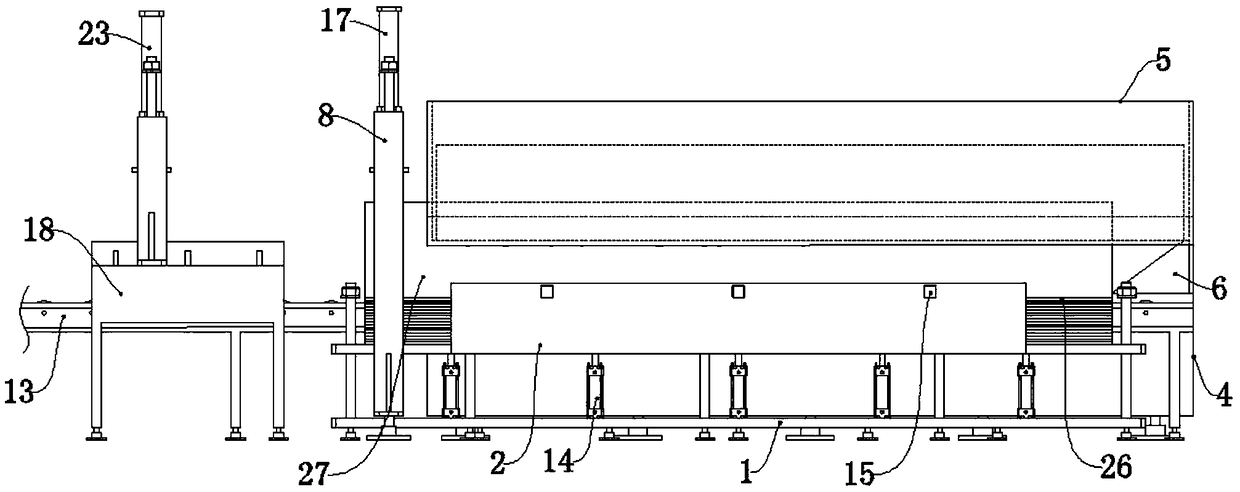
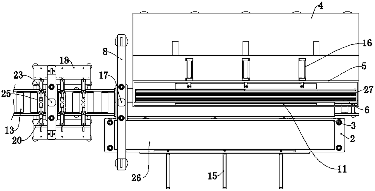
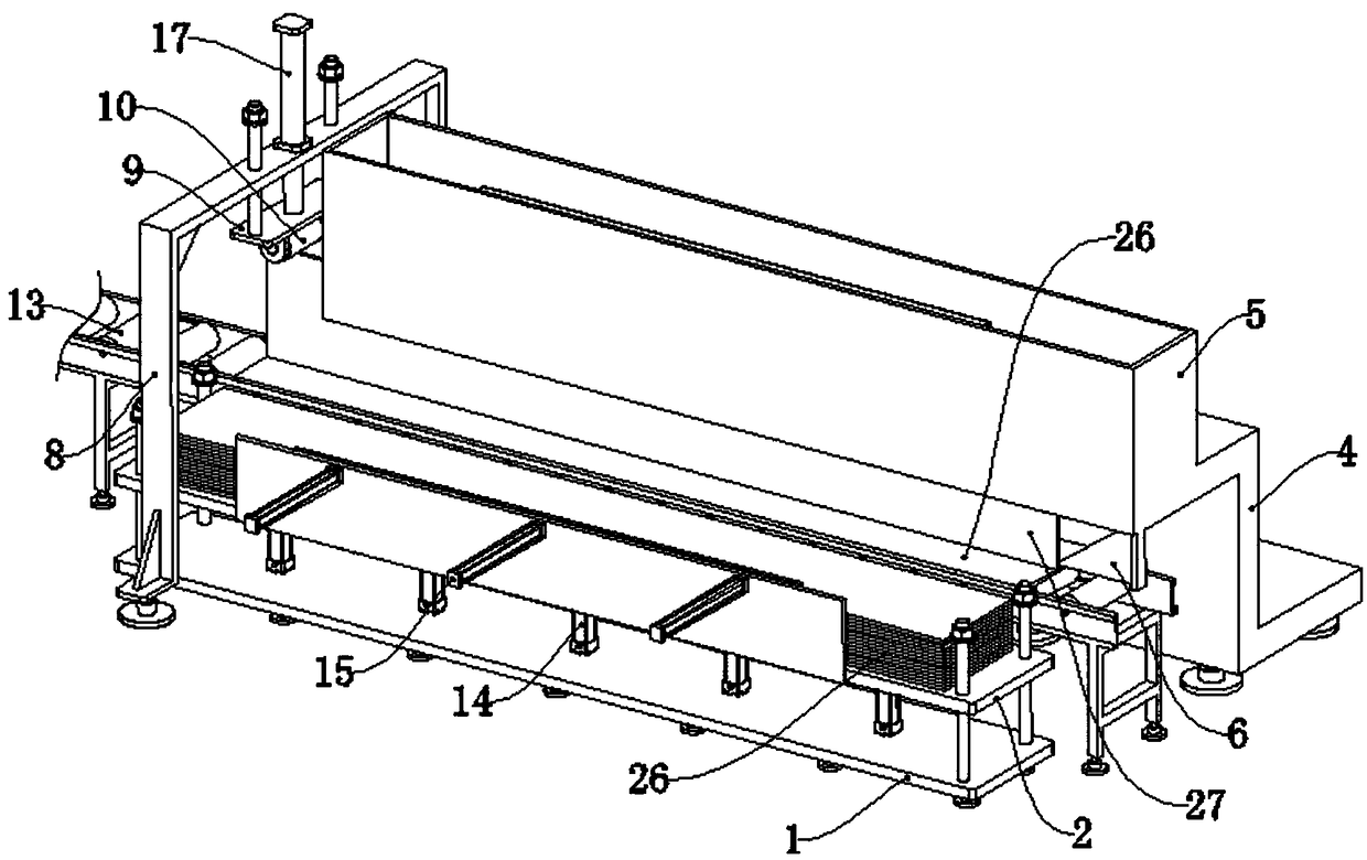
[0022] Figure 1 to Figure 8 It shows the T-shaped steel erecting machine of the present invention, a T-shaped steel erecting machine, which includes an electric roller table 13, a wing plate feeding device, a web feeding device, a vertical pre-compression device and a centering device.

[0023] The wing plate feeding device comprises a wing plate feeding device support 1, a wing plate supporting bracket 2, a wing plate supporting bracket lifting hydraulic cylinder 14 and a wing plate horizontally pushing hydraulic cylinder 15. The blade feeding device bracket 1 is located on one side of the electric roller table 13, and the blade supporting bracket 2 can be vertically slidably mounted on the blade feeding device bracket 1. A baffle plate 3 is provided on the side of the wi...


PUM


Abstract

The invention relates to the technical field of steel structure processing equipment, and specifically relates to a T-shaped steel assembly machine. The T-shaped steel assembly machine comprises a conveyor, a wing plate feeding device, a web feeding device, a vertical prepressing device and a centering device, wherein the wing plate feeding device comprises a wing plate feeding device bracket, a wing plate support frame, a wing plate support frame lifting device and a wing plate horizontal pushing device; the web feeding device comprises a web feeding device bracket, a web box, a web horizontal pushing device and a guide inclined block; the vertical prepressing device is arranged downstream the wing plate feeding device and the web feeding device in the conveying direction of the conveyor,and the vertical prepressing device comprises a prepressing device bracket, a prepressing roller bracket, a prepressing roller and a prepressing roller bracket lifting device; and the centering device is arranged downstream the vertical prepressing device in the conveying direction of the conveyor. According to the T-shaped steel assembly machine, the production efficiency can be improved, the labor intensity of workers is reduced, and webs and wing plates are prevented from misplacing due to relative sliding during transportation.

Description

technical field [0001] The invention relates to the technical field of steel structure processing equipment, in particular to a T-shaped steel assembly machine. Background technique [0002] T-shaped steel is a kind of steel whose cross-section is the English letter "T". T-shaped steel is divided into hot-rolled T-shaped steel and welded T-shaped steel. Board position accuracy to aid in soldering. [0003] The invention patent with application number 201710084439.0 discloses an automatic assembly machine for H-shaped steel, which can be used for welding T-shaped steel, including frame, conveying guide rail, centering device, pressing device, feeding device, etc. , its working process is referring to paragraph 0053 and paragraph 0056 of the description of this patent. This H-shaped steel automatic assembly machine has the following disadvantages: (1) "The wing plate in the wing plate material storage frame is adsorbed to the feeding wheel by the first electromagnet", becaus...

Claims


Application Information

Patent Timeline
Patent Type & Authority Applications(China)
IPC IPC(8): B23P19/00B23K37/00
CPCB23K37/00B23P19/00B23P19/001
Inventor 高学书孙颖
Owner SHAN DONG JUXIN GRP STEEL STRUCTURE CO LTD
Why Eureka
Try Eureka