Structure for preventing pulverized coal leakage of swirl burner

A swirl burner, pulverized coal technology, applied in burners, burners burning powder fuel, combustion methods, etc., can solve the problems of internal leakage of pulverized coal, easy loosening of bolts, leakage of pulverized coal, etc. Inner leakage of burner pulverized coal, preventing outer leakage of burner pulverized coal, and the effect of wide working pressure range

Active Publication Date: 2018-10-16
DONGFANG BOILER GROUP OF DONGFANG ELECTRIC CORP
View PDF10 Cites 2 Cited by
  • Summary
  • Abstract
  • Description
  • Claims
  • Application Information

AI Technical Summary

Problems solved by technology

Due to the shaking of the pipeline during operation, the bolts are easy to loosen after a long period of operation, which may also cause a gap between the flange surfaces, resulting in coal powder leakage
At present, measures to prevent pulverized coal leakage have been considered in the design of the swirl burner, such as using ceramic fiber mats to seal the interface between the burner and the pulverized coal pipeline, or welding the interface between the burner and the pulverized coal pipeline, but it cannot be completely avoided Coal powder leaks, and the leaked coal powder will adhere to the surface of the burner, especially for lignite, which is very easy to catch fire, which will easily cause the burner panel to burn red and see an open flame
If the interface between the burner and the pulverized coal pipeline is welded, although the leakage of pulverized coal can be effectively prevented, the burner cannot be pulled out for maintenance, which brings inconvenience to the operation and maintenance of the combustion equipment
2. Internal leakage of burner pulverized coal
However, when the output of the coal mill or the fan fluctuates or the pulverized coal pipeline is blocked, the primary wind speed decreases, the ignition point is very close to the burner, and part of the pulverized coal will be drawn back to the nozzle of the burner, burning near the nozzle and causing the nozzle to burn. Deformation causes part of the pulverized coal to leak out of the primary air assembly of the burner (primary / secondary air interlayer), and catch fire in the burner

Method used


Image

  • Structure for preventing pulverized coal leakage of swirl burner
  • Structure for preventing pulverized coal leakage of swirl burner
  • Structure for preventing pulverized coal leakage of swirl burner

Examples


Embodiment 1

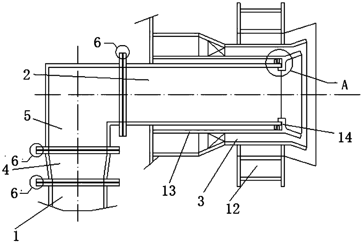
[0022] Such as figure 1 Shown, the structure that prevents the pulverized coal 15 leakage of swirl burner of the present invention, both can be used for the swirl burner of burning lignite, also can be used for the swirl burner of burning lignite, with the burning lignite of 1000MW grade Take the pulverized coal 15 boiler as an example. It is equipped with 56 swirl burners. The inspection workload of 56 burners is very heavy. At the same time, the number of burners is large, and the risk of leakage will also be great. These 56 swirl burners can all adopt the invented structure for preventing the leakage of pulverized coal 15 of the swirl burners, which can effectively improve the safety and reliability of the unit.

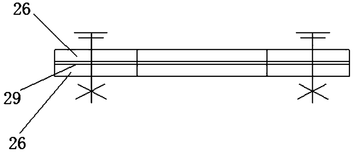
[0023] Existing burners such as figure 2 As shown, under normal circumstances, the ignition point is far away from the nozzle of the burner, and the flame of entrainment and backflow will not bring the pulverized coal 15 back to the burner. There is no gap betwe...


PUM


Abstract

The invention relates to the technical field of boilers and discloses a structure for preventing pulverized coal leakage of a swirl burner. The structure comprises a pulverized coal pipe, a primary air pipe and a secondary air pipe. The pulverized coal pipe is communicated with the primary air pipe through a connecting pipe. The connecting pipe is connected with the pulverized coal pipe through aflange, and the connecting pipe is connected with the primary air pipe through a flange. A nozzle of the primary air pipe is communicated with the secondary air pipe, an interlayer is arranged betweenthe primary air pipe and the secondary air pipe, and the primary air pipe, the secondary air pipe and the interlayer are coaxially arranged. A baffle blocking the nozzle of the primary air pipe is arranged at the end of the interlayer, and each flange comprises a convex flange and a concave flange which are matched and connected. The connecting faces of the convex flanges are convex faces, and the connecting faces of the concave flanges are concave faces. A flexible gasket is arranged between each convex flange and the corresponding concave flange. Each flange is configured to the concave-convex face, each gasket is not extruded easily, centering is facilitated during assembly, the working pressure range is wider than that of a flat-face flange, the airtightness is better, and pulverizedcoal leakage of the burner can be prevented.

Description

technical field [0001] The invention relates to the technical field of boilers, in particular to a structure for preventing pulverized coal leakage of a swirl burner. Background technique [0002] Swirl burner The swirl burner is formed by a primary air duct, a secondary air duct, and a swirler. A central air duct is installed in the primary air duct, and a small stream of pulverized coal or oil mist or gas is introduced into the central air duct. Directly entering the recirculation zone, it will be ignited first, with stable combustion and small fluctuations in ignition pressure. It is widely used in high-parameter and large-capacity coal-fired power plant boilers. Since the burner area in the coal-fired boiler is the highest temperature area in the furnace, the burner is always in contact with the high-temperature flame and flue gas. When the burner is put into operation, the air volume passing through the burner is large enough to cool metal parts such as primary air comp...

Claims


Application Information

Patent Timeline
Patent Type & Authority Applications(China)
IPC IPC(8): F23D1/02
CPCF23D1/02
Inventor 朱骅安仁敏谢佳李铁
Owner DONGFANG BOILER GROUP OF DONGFANG ELECTRIC CORP
Why Eureka
Try Eureka