VPH transmissive spectrometer spectral line bend correction system

A bending correction and spectrometer technology, applied in the field of spectroscopy, can solve the problems of high cost of prism grating, unfavorable promotion, affecting the spectral resolution and spatial resolution of the system, and achieve the effect of simple light speed and solving the problem of spectral line bending.

Pending Publication Date: 2018-10-16
安徽创谱仪器科技有限公司
View PDF4 Cites 1 Cited by
  • Summary
  • Abstract
  • Description
  • Claims
  • Application Information

AI Technical Summary

Problems solved by technology

[0003] However, for the imaging spectrometer, due to its own optical characteristics, the light coming out of the incident slit is no longer a vertical line after being imaged on the CCD, and the light spot at the off-center position and the original main optical path lead to the spectral line bending
This kind of spectral line bending will not only affect the spectral resolution and spatial resolution of the system, but also cause great trouble to the user's data processing
For this kind of spectral line bending, the traditional method is to calibrate the wavelength of each column of the area array CCD, so as to obtain the wavelength information of each pixel in the entire area array area, or to calibrate the calibration formula of several columns connected to each other, and obtain the entire CCD through the difference. Wavelength information in the area of ​​the area array, but this method cannot fundamentally correct the bending of the spectral line, and there is also a way to correct the bending of the spectral line by adding a prism grating, but the cost of the prism grating is too expensive, which is not conducive to popularization

Method used


Image

  • VPH transmissive spectrometer spectral line bend correction system
  • VPH transmissive spectrometer spectral line bend correction system
  • VPH transmissive spectrometer spectral line bend correction system

Examples


Embodiment Construction

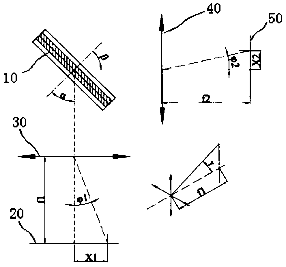
[0012] figure 1 The optical schematic diagram of a typical VPH system is shown, where f1 is the length of the incident arm; f2 is the length of the exit arm; α is the incident angle of the grating; β is the diffraction angle of the grating; X1 is the distance from the main optical axis in the horizontal direction of the incident slit; Φ1 is the angle of the incident slit from the main optical axis in the horizontal direction; X2 is the distance of the diffraction spot from the main optical axis in the horizontal direction; Φ2 is the angle of the diffraction spot from the main optical axis in the horizontal direction; horn.

[0013] Design Optical System

[0014] The diffraction equation of the grating is:

[0015] Νmλ=cos(γ)(sin(α+φ1)+(sin(β+φ2)))

[0016] N is the linear density of the grating, λ is the wavelength of the incident light, and m is the diffraction order of the grating.

[0017] On the main optical axis, Φ1=Φ1=γ=0, the diffraction equation of the grating is: ...


PUM


Abstract

The invention discloses a VPH transmissive spectrometer spectral line bend correction system. The system comprises an entrance slit, a collimating lens assembly, a VPH grating, a focusing lens assembly and a CCD. Incident light enters a VPH transmissive spectrometer through the entrance slit, and is collimated by the collimating lens assembly, and split by the VPH grating through diffraction; thediffracted light is focused to a CCD imaging unit by a focusing lens. A bent slit is designed through calculation for a specific optical system, and the bent entrance slit is utilized to compensate the bent spectral line of the whole system, so as to realize correction of the bent spectrometer spectral line. This method is simple and effective, has no impact on performance of the instrument, and cannot cause additional data processing cost to users. The VPH transmissive spectrometer spectral line bend correction system solves the problem of spectral line bend of the spectrometer from a sourceof system design, and can be used for actual test requirements.

Description

technical field [0001] The invention relates to the technical field of spectroscopy, in particular to a method for correcting spectral line bending of a VPH transmission spectrometer. Background technique [0002] Imaging spectrometer is an instrument used to obtain two-dimensional spatial information and spectral information of the target, and has been widely used in various fields. Compared with the conventional reflective diffraction grating, the volume holographic grating (VPH) has the maximum diffraction efficiency of stray light with extremely low efficiency. The imaging spectrometer developed by using the VPH grating combined with the lens system has a higher imaging performance than other imaging spectrometers. Quality and detection efficiency, its application is also more and more extensive, such as detection of Dα plasma spectrum in ITER, Raman spectrum detection and so on. [0003] However, for the imaging spectrometer, due to its own optical characteristics, the...

Claims


Application Information

Patent Timeline
Patent Type & Authority Applications(China)
IPC IPC(8): G01J3/28G01J3/02
CPCG01J3/0297G01J3/2823
Inventor 李朝阳吴华峰安宁徐勇
Owner 安徽创谱仪器科技有限公司
Why Eureka
Try Eureka