A Slit Iris Diaphragm Based on Air Float Guide

An air-flotation-guided, slit-type technology, applied in optics, optical components, instruments, etc., can solve the problems of multiple motion links, poor rotational stiffness, and bulky volume, so as to improve motion and positioning accuracy, avoid collisions and damage, The effect of increasing speed and efficiency

Active Publication Date: 2019-05-07
HARBIN INST OF TECH
View PDF9 Cites 0 Cited by
  • Summary
  • Abstract
  • Description
  • Claims
  • Application Information

AI Technical Summary

Problems solved by technology

The linear motion reference in its exposure system adopts a mechanical guide rail structure and reaches 40m / s 2 Acceleration movement of (Y.B.Patrick Kwan, Erik L.Loopstra. Nullifying Acceleration Forces in Nano-Positioning Stages for Sub-0.1mm Lithography Tool for 300mm Wafers[J].proceeding of SPIC: Optical Microlithography, 2010,4346:544-557) ; But with the development of the chip manufacturing industry, traditional sliding / rolling guideways are difficult to meet the requirements of high acceleration motion and working temperature stability
[0004] Patent CN201220540610 "Multilayer Air Float Suspension Device for Two-Dimensional Frictionless Long-distance Movement" proposes an air flotation-guided suspension movement device, which mainly includes a single-layer suspension device and an unfolding test frame, and the single-layer suspension device Including supporting parts, air bearing moving parts, detection parts and guide rail system, air bearing moving parts include longitudinal air bearing sleeves, two horizontal air bearing sleeves, two air bearing seats, telescopic air pipes, horizontal air bearing shafts and hanging Tooling; this device can realize large displacement and long-distance follow-up movement, and satisfy the cooperative movement between multi-layer hanging devices; but the inventive device is a follow-up movement device, which cannot guarantee the movement accuracy, and needs to be installed on the unfolding test frame used on the Internet, the structure is not compact enough
[0005] Patent CN201310436356 "Air Suspension Type Three-Dimensional Unfolding Experimental Device" proposes a three-dimensional motion device with high positioning accuracy and fast response speed, which mainly includes more than a dozen air floating motion mechanisms correspondingly distributed in space, and with the help of pulleys, slings, counterweights, etc. The mechanism is installed inside the support frame; however, although the device can meet a certain motion accuracy, due to many motion links, it cannot ensure fast and accurate displacement response at the output end under high-frequency motion state, and the structure is not compact enough
[0006] Patent CN201410839808 "A double-air-floating rail-type grating scoring tool holder driving device" proposes a small one-dimensional motion device, which mainly includes two sets of air-floating rails installed in parallel, and is improved by fixing the air-floating sliding sleeve. The movement stability of the marking tool holder; the device can realize high-speed and high-frequency movement, but compared with the displacement output end of the device, such as the tool holder adapter plate and the marking tool holder, the air bearing guide rail is too large, so the unit Less rotational stiffness in area and requires toolholder counterweights for balance
[0007] Patent CN201610130635 "Double-sided air flotation transport platform" and patent CN201710832517 "A motion platform based on H-shaped air flotation guide rails" respectively propose air flotation devices to realize two-dimensional motion, which can achieve high motion while taking into account stability and positioning accuracy, but the use methods of the two devices are mounted, and cannot be used for suspension or cantilever sports occasions, and for the exposure system of the lithography machine, the volume is too large
[0008] The common disadvantage of the above-mentioned inventions is that none of them can realize window scanning in any range in the plane through the independent movement of the four coplanar diaphragm plates.

Method used


Image

  • A Slit Iris Diaphragm Based on Air Float Guide
  • A Slit Iris Diaphragm Based on Air Float Guide
  • A Slit Iris Diaphragm Based on Air Float Guide

Examples


Embodiment Construction

[0029]Embodiments of the present invention will be described in detail below in conjunction with the accompanying drawings.

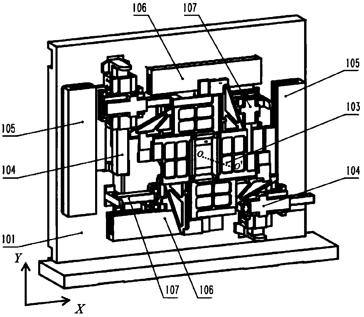
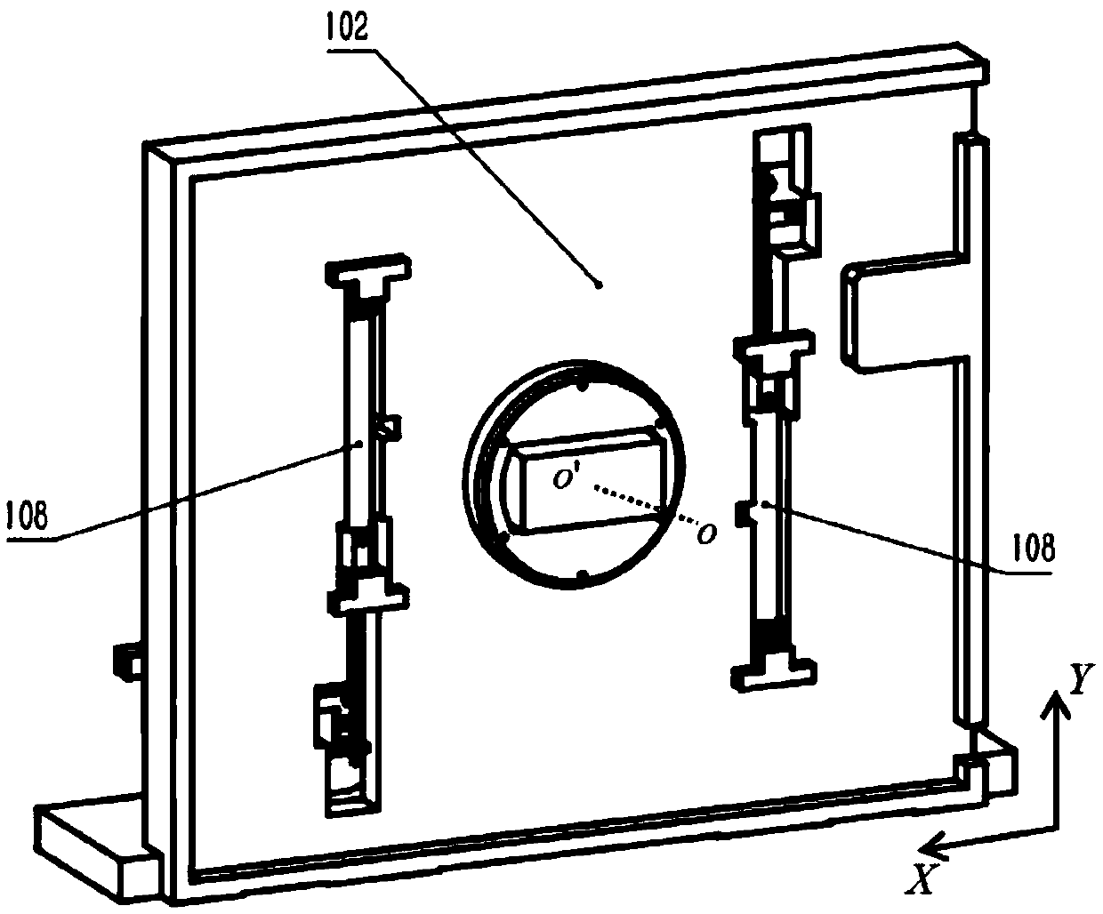
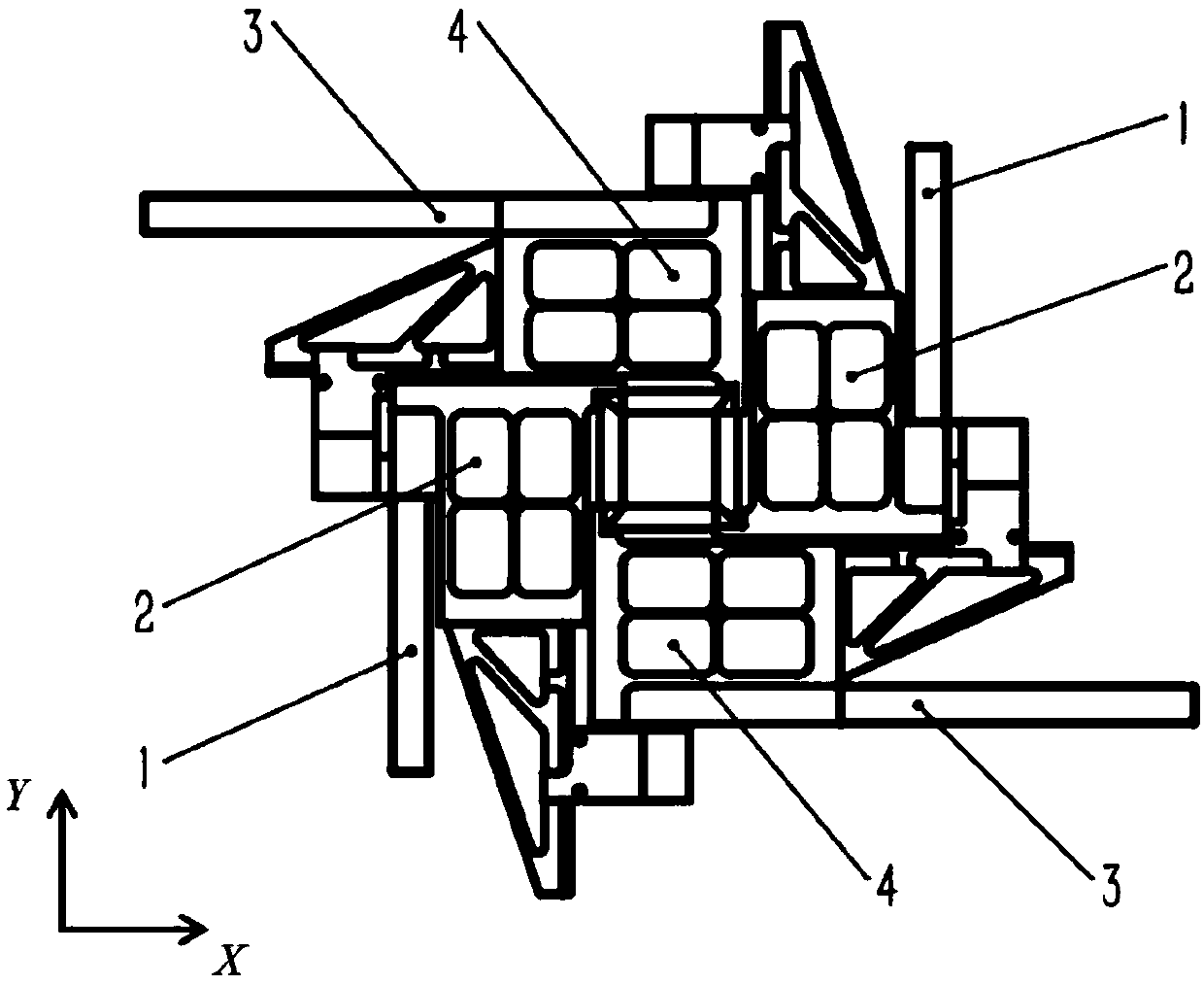
[0030] A slit-type iris diaphragm based on air-floating guidance. Two X-direction drive control units 106 arranged in parallel and two Y-direction drive control units arranged in parallel are respectively installed on the front panel 101 of the device. 105 , two X-direction support guide units 107 arranged parallel to each other, two Y-direction support guide units 104 and the aperture window 103 arranged parallel to each other. Two mutually parallel gravity compensation units 108 are installed on the back panel 102, and the aperture window 103 is composed of two correspondingly configured X-direction aperture plates 4, two correspondingly configured Y-direction aperture plates 2, and two correspondingly configured Y-direction aperture plates. The configured X-direction driven air-bearing guide rail 3 and two correspondingly configured Y-direction drive...


PUM


Abstract

The invention discloses a slit-type variable aperture based on air bearing guidance; the front panel of the device is equipped with 2 X-direction drive control units, 2 Y-direction drive control units, 2 X-direction support guide units, 2 Y-direction support guide unit and diaphragm window; 2 gravity compensation units are installed on the back panel; the diaphragm window consists of 2 X-direction diaphragm plates, 2 Y-direction diaphragm plates, 2 X-direction driven air bearing guide rails and 2 A Y-direction driven air bearing guide rail; the paired units are rotationally symmetrical with respect to the optical central axis oo' of the system; the device includes 4 support guide units based on the air bearing principle, guiding the 4 driven guide rails, and passing through The drive control unit and the gravity compensation unit control the four diaphragm plates respectively, and the diaphragm plates connect end to end to form a coplanar rectangular window, and finally realize scanning in any range in the plane; the invention establishes a high-precision , High stability air bearing guided slit iris.

Description

technical field [0001] The invention belongs to the technical field of precision instruments and machinery, and in particular relates to a slit-type variable aperture based on air-floating guides. Background technique [0002] In recent years, as the advanced chip manufacturing industry gradually develops towards functional integration and volume miniaturization, the gas static pressure linear motion benchmark has become one of the key components in cutting-edge lithography machines due to its remarkable advantages such as high speed and high precision; The high-speed, high-acceleration, and high-motion-precision requirements of the diaphragm in the exposure system of the engraving machine put forward the requirements for high load-carrying capacity and high rotational stiffness of the gas-static guide rail in the gas-static linear motion benchmark; in order to avoid the linear motion mechanism from blocking Optical path or touch optical device, the diaphragm plate is instal...

Claims


Application Information

Patent Timeline
Patent Type & Authority Patents(China)
IPC IPC(8): G02B26/02
CPCG02B26/02
Inventor 温众普吴剑威彬德尔张银谭久彬
Owner HARBIN INST OF TECH
Why Eureka
Try Eureka