
Ozone microbubble catalytic oxidation device and application thereof

A catalytic oxidation and micro-bubble technology, which is applied in the fields of oxidized water/sewage treatment, chemical instruments and methods, water/sewage treatment, etc., can solve the problem that ozone bubbles are difficult to reach the level of micro-bubbles, the ozone utilization rate is difficult to guarantee, and the ozone utilization rate is low. and other problems, to achieve the effect of facilitating gas-liquid mixing and transmission, improving ozone utilization, and promoting hydraulic disturbance

Pending Publication Date: 2018-10-23
JIACHENG ENVIRONMENTAL PROTECTION ENG CO LTD
View PDF4 Cites 7 Cited by
  • Summary
  • Abstract
  • Description
  • Claims
  • Application Information

AI Technical Summary

Problems solved by technology

The aeration method still adopts the aeration plate method, the ozone bubbles are difficult to reach the level of micro-bubbles, and the ozone utilization rate is also difficult to guarantee; the catalyst unit adopts a single activated carbon, which is not adaptable to complex water quality or fluctuating water quality
[0013] To sum up, although there are many discussions and researches on the catalytic oxidation of microbubble ozone at this stage, most of the microporous aeration methods proposed are aeration pans and aeration heads, which have low ozone utilization efficiency and weak oxidation ability.

Method used


Image

  • Ozone microbubble catalytic oxidation device and application thereof
  • Ozone microbubble catalytic oxidation device and application thereof
  • Ozone microbubble catalytic oxidation device and application thereof

Examples


Embodiment Construction

[0076] The present invention will be further described below in conjunction with the examples, but it should not be interpreted as a limitation of the present invention. The protection scope of the present invention is based on the contents recorded in the claims. protection scope of the present invention.

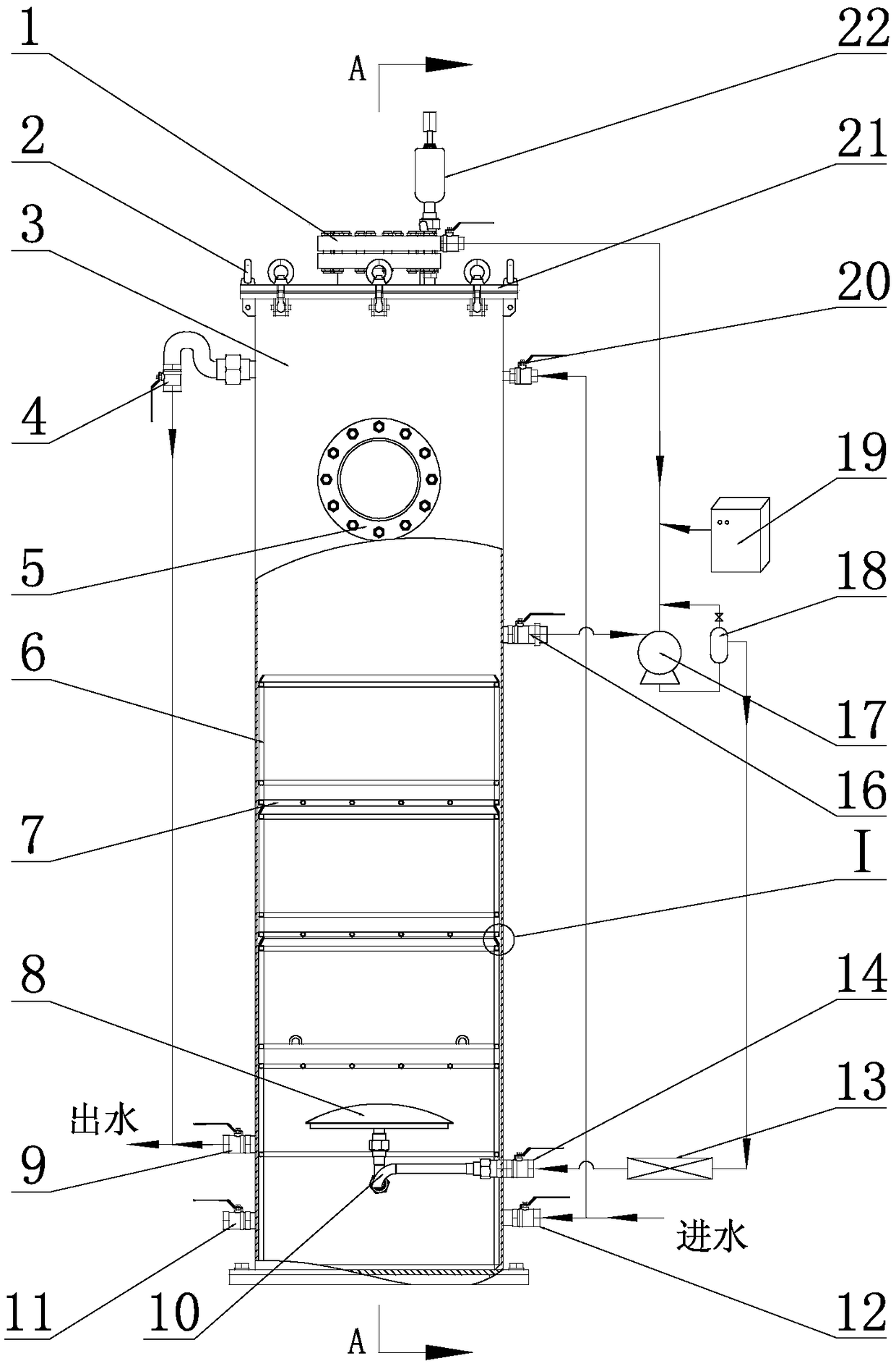
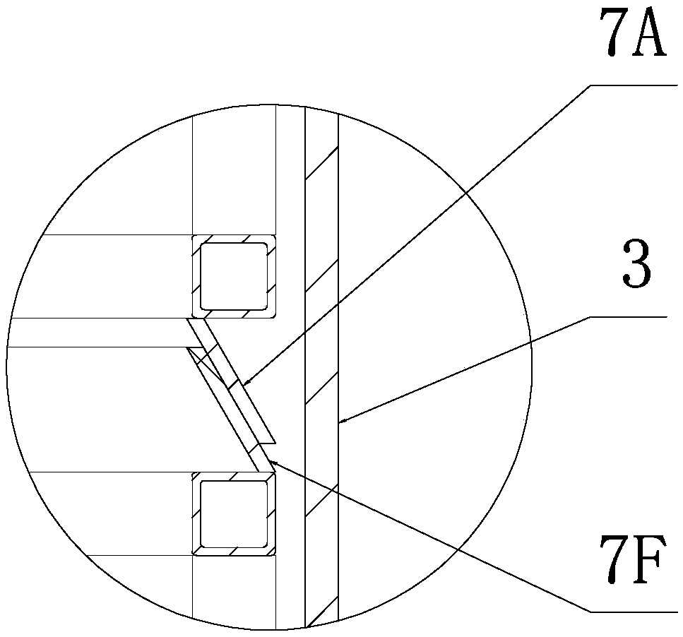
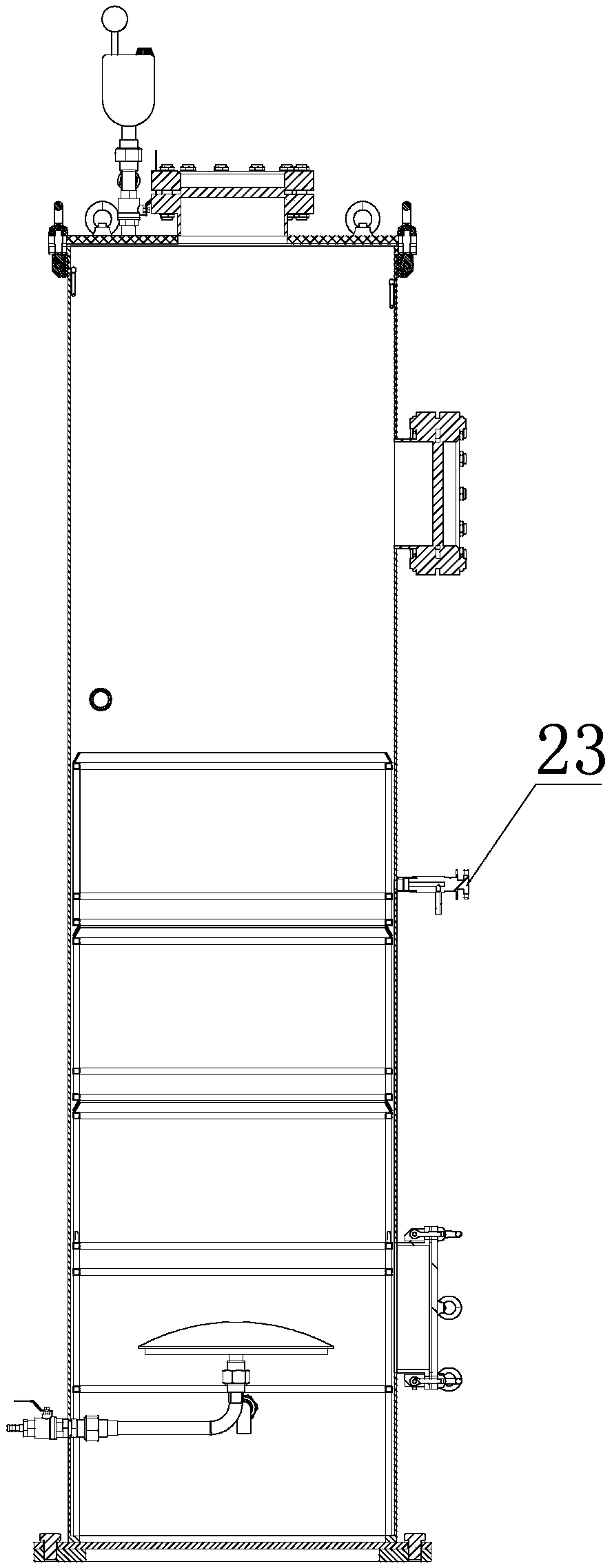
[0077] The overall structure of this embodiment is as shown in the figure, wherein the ozone microbubble catalytic oxidation device includes a tower body 3, an ozone generator 19 that provides ozone for the tower body 3, and a catalytic unit that provides a catalyst for the tower body 3, and the tower body 3 is provided with Water inlet, water outlet, described water inlet comprises the upper water inlet 20, the lower water inlet 12 that is opened on the tower body 3 side walls above and below, and the water outlet includes the upper water outlet 4, the lower water outlet 9 above and below the side wall Ozone generator 19 is delivered to microbubble generator 13 with the g...


PUM


Abstract

The invention belongs to sewage treatment in environmental protection engineering, and in particular, relates to an ozone microbubble catalytic oxidation device and an application thereof. The ozone micro-bubble catalytic oxidation device comprises a tower body, an ozone generator and a catalytic unit. The tower body is equipped with water inlets and water outlets. The water inlets include an upper water inlet arranged at the upper part of the side wall of the tower body and a lower water inlet arranged at the lower part of the side wall of the tower body, the water outlets include an upper water outlet arranged at the upper part of the side wall of the tower body and a lower water outlet arranged at the lower part of the side wall of the tower body. The ozone generator conveys a gas-liquid mixture to a microbubble generator through a gas-liquid mixing pump, and the output end of the microbubble generator is connected with an inlet of a circulating pipeline of the microbubble generatorbelow the tower body; the catalytic unit adopts at least two layers of catalyst boxes in longitudinal interval and horizontal arrangement, the catalyst boxes are arranged in the tower body through brackets, and an outlet, arranged on the side wall of the tower body above the catalytic unit, of the circulating pipeline of the microbubble generator is connected with the gas-liquid mixing pump. Thetechnical problem of low ozone utilization rate of the prior art is effectively solved, and the ozone microbubble catalytic oxidation device has the advantages of compact structure, high ozone utilization rate and the like.

Description

technical field [0001] The invention belongs to sewage treatment in environmental protection engineering, in particular to an ozone microbubble catalytic oxidation device and its application. Background technique [0002] With the development of urbanization and the increasing of industrial production, the generated urban sewage and industrial wastewater have become an important cause of water environment pollution. Water pollution poses increasingly severe threats to the ecological environment and people's water safety and health. With the concept of harmonious coexistence between man and nature gradually becoming popular and the introduction of water pollution prevention and control policies in the new era, the requirements and difficulties for sewage treatment technology are gradually increasing. [0003] Industrial wastewater after conventional biological treatment still contains some refractory organic substances, such as phenols, benzene, cyanide, pesticides, etc., so...

Claims


Application Information

Patent Timeline
IPC IPC(8): C02F1/78
CPCC02F1/725C02F1/78C02F2201/784
Inventor 王晓磊张进学押玉荣吴江渤安少锋李小亚王立川李兴美
Owner JIACHENG ENVIRONMENTAL PROTECTION ENG CO LTD
Learn More